Innosilicon and Aladdin Miner Portable Test Fixture User Manual
By THANOS MINING
April 8th, 2022
Innosilicon and Aladdin Series Portable Test Fixture User Manual
I. Function description
This test fixture can be separated from the computer to test the hash board and digital power supply independently. Hashboard test supports models Innosilicon T1, T2TS, T2TH, T2TZ, Aladdin L1, L2HF, L2HU, L2SU, L2HL. Power supply test supports all series of digital power supplies from Innosilicon. Without removing the shelf or disassembling the miner, you can check and determine whether the miner's hash board and power supply are faulty, and the maintenance mode can accurately locate the cause of the hash board failure, which greatly improves the maintenance and operation and maintenance efficiency of the miner.
II. Test Fixture interface description
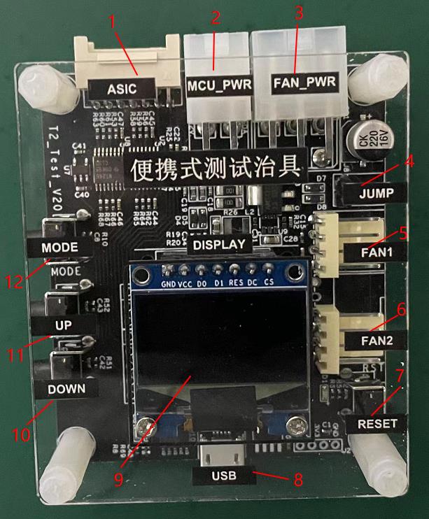 1: Hash board interface;
2: 4Pin power supply and power communication interface;
3: 6Pin fan power supply interface;
4: The main board spares the power jumper (when testing T1/L1, the test fixture needs to be powered from the fan power supply interface before short-circuiting the jumper, otherwise it can be kept disconnected);
5: 4Pin fan driver interface 1;
6: 4/6Pin fan driver interface 2;
7: Test Fixture reset button;
8: USB communication interface (connected to PC serial port at 115200 baud rate, detailed test information can be output);
9: Brief test information display screen;
10: Up function key;
11: Down function key;
12: Debug mode function button;
III. Instructions for use
3.1 Power Test
1) Power quick test
When only testing the digital power supply, just insert the 4Pin power supply line of the digital power supply into the interface 2 of the test fixture, and then turn on the digital power switch to be tested. Wait for about 8 seconds, observe the information displayed on the display, and then judge whether the power supply to be tested is normal.
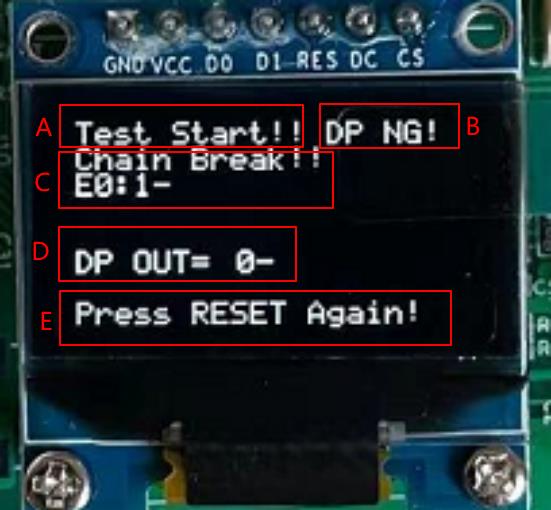
 Display area content description:
A: "Test Start!!" test start prompt
B: "DP NG!" "DP OK!" The power communication test result shows that NG-communication fails, OK-communication is normal
C: "Chain Break!! E0:1-" Hashboard test result display area. When measuring the power supply, it can be ignored.
D: "DP OUT= 0-" "DP OUT=1565-" power output voltage value display. represent 0V and 15.65V, respectively.
(B area and D area respectively indicate the communication function and voltage output function of the power supply)
E: "Press RESET Again" test end prompt, if you need to repeat the test, press the reset button 7.
2) Power depth test
Under normal circumstances, it will not enter the power supply full-process test mode. Only when the UP (11 key) and DOWN (10 key) buttons are pressed and turned on before power-on, the test fixture will enter the power depth test mode. In this mode, the MODE key can control the power switch, the UP and DOWN keys can control the output voltage of the power supply, and the voltage is divided into 0~31 gears and can be adjusted.
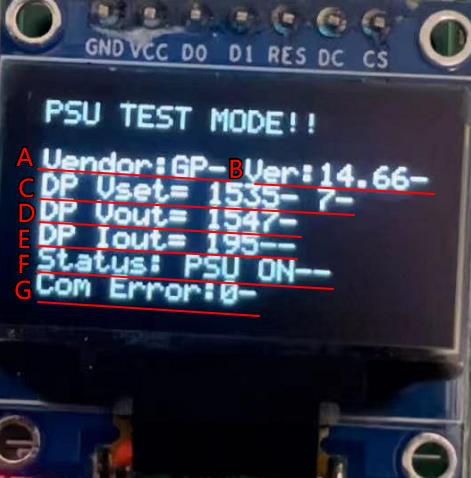 Display area content description:
A: "Vendor: GP" power supply manufacturer code
(GP: Gaosbao AR: Anrui QB: Qianben)
B: "Ver:14.66" power supply firmware version is 14.66
C: "DP Vset=1535 -7 " The output voltage of the power supply is set to 15.35V in 7th gear.
D: "DP Vout=1547" The actual output voltage of the power supply is 15.47V
E: "DP Iout=195" The current actual output current of the power supply is 1.95A
F: "Status: PSU ON" power output status, ON means open, OFF means close.
G: "Com Error:0" Power data communication error count. If not 0, then
Indicates that there is a communication failure in the power supply and the power supply is not under the control of the control board.
3.2 Hashboard Test
1) Quick link test (this mode makes the hash board less hot, and the fan power cable and cooling fan can be omitted)
When the USB serial port is not connected, you can view the test results through the display screen. When the USB serial port is connected, find the correct COM port, open the serial port with a baud rate of 115200, and view the test details.
 A: "Chain OK!" Hashboard chain link prompt.
B: "Chips: 140-" indicates the number of chips on the computing board, a total of 140.
C: "Vol Read OK! 454-" prompt of successful reading of hash power chip voltage.
The average voltage per stage is 454mV.
"TEMP Read OK!16-" The temperature of the computing power chip is successfully read.
The average temperature of each piece is 16 ℃.
D: "Test PASS!" The hash board test conclusion is passed.
2) Full-process test (except for mining test, this mode will make the hash board generate a lot of heat, and the fan power supply cable and cooling fan must be connected to maintain a good cooling environment)
Under normal circumstances, it will not enter the full-process test mode, only when the test fixture is connected to the computer through USB, and press and hold the debug mode function button 12 before power-on, and then release it after the serial port prints a message indicating the content below.
"----Enter Debug Mode!----"
"Please input PowerOn VID value(0~31, default 0):"
LED display shows "DEBUG MODE:."
At this point, it enters the full process test mode.
(Before entering this mode, please connect the power board interface of the test fixture to the board to be tested, and connect the fan power supply and fan drive port, and then power on)
Step 1: "Please input PowerOn VID value(0~31, default 0):"
According to the prompt, use the keyboard to set the output voltage of the power supply during the test, that is, the startup voltage of the hash board. Enter 0~31 and press Enter to confirm, the smaller the value, the higher the output voltage (12V~16V). If it exceeds the range, you need to re-enter.
Step 2: "Please input working PLL frequency MHz of Board 0(120~1400, default 0):"
Use the keyboard to set the running frequency of the hash board during the test according to the prompts. After inputting 120~1400, press the Enter key to confirm, the larger the value, the greater the power consumption. If it exceeds the range, you need to re-enter.
Step 3: "Press enter to set pll!"
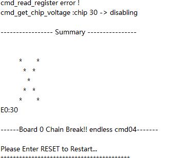
After successfully reading the voltage and temperature of the hash board, the above information will be prompted before increasing the operating frequency. Press Enter to confirm the frequency increase. If the hash board chain fails, enter the maintenance mode, send maintenance instructions to the hash board without interruption, and keep the power supply uninterrupted. You can use an oscilloscope to find the faulty chip step by step.
Step 4: "Press enter to change vid!"
After the operating frequency of the computing power board is increased to the specified value, the above prompt appears, and the power output voltage can be changed automatically 5 times, and the voltage change of the computing power chip can be observed for each change.
Step 5: When the test is over, observe the projected output of the test result.
 Innosilicon Aladdin test fixture product link: Innosilicon Aladdin Test Fixture

Previous
How to choose the right miner fan simulator?
Read More
Next
Antminer/Whatsminer PSU Wake-up/Startup Tester Manual
Read More


