The introduction
In order to help and guide the site operation and maintenance personnel to improve the maintenance efficiency and
accuracy of the power supply, combining with the after-sales maintenance data of the power supply, this
maintenance manual is formulated for reference.
Scope of application
PSU3300-03 (3300W)
Input:200-285VAC 50/60Hz 16A Max
Output:11.5V-14.5V ⎓ 3100W
12V ⎓ 200W
RSPOWER: PSU3300-03 PLUS (3600W)
Input:185-285VAC 50/60Hz 16A Max
Output:11.5V-14.5V ⎓ 3400W
12V ⎓ 200W
The product principle
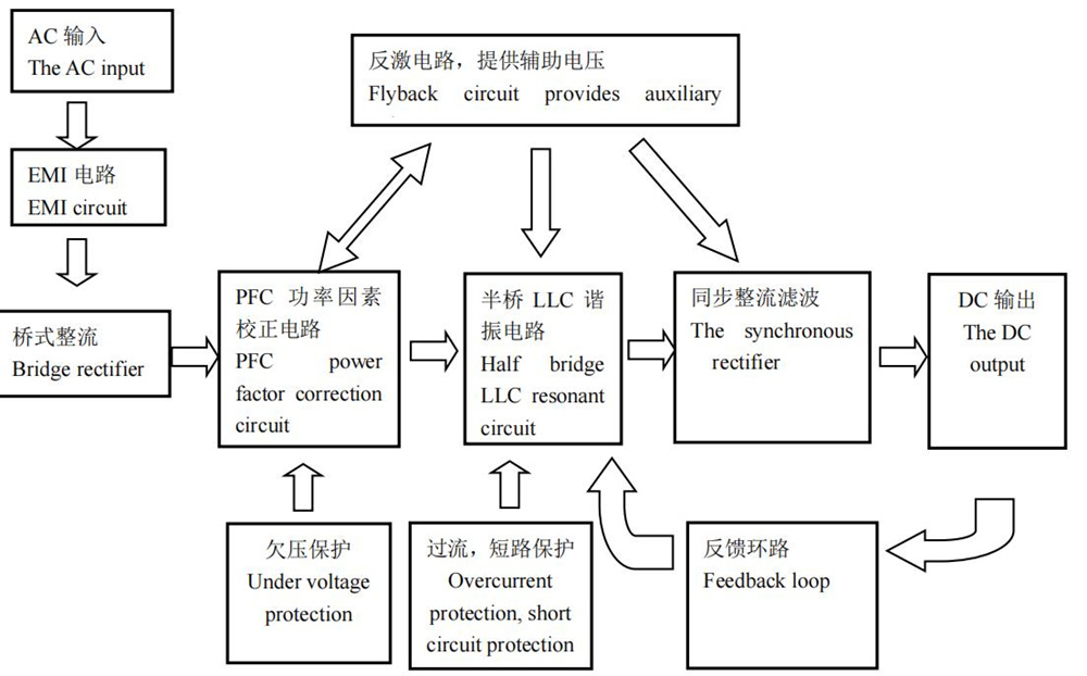
The main circuits of the power supply are: EMI circuit, bridge rectifier, power correction circuit, flyback circuit,
auxiliary half-bridge LLC resonant circuit, auxiliary synchronous rectifier filter circuit, main half-bridge LLC
resonant circuit, main synchronous rectifier filter circuit, MCU control circuit, protection circuit.
①Power on,the input AC voltage is translated to DC voltage through the EMI circuit and the bridge rectify circuit.
②DC Voltage generates 18VCC through flyback circuit;
③18VCC is converted to to supply relay, auxiliary circuit LLC2 IC, main circuit LLC1 IC , PFC IC ;
④After the PFC chip works, the PFC voltage is boosted, the main circuit LLC 1 IC and auxiliary circuit LLC2 IC
begin to work.
⑤After the main output LLC1 chip works, there is a main output voltage through LLC resonant circuit, and then the
synchronous rectification works;
⑥After the auxiliary circuit LLC2 IC works, there is a auxiliary output voltage through LLC resonant circuit, and
then the synchronous rectification works;
⑦The auxiliary voltage is translated to supply MCU IC, Which provides software communication, control, protection
function.
Power Circuit Block Diagram
Common failure analysis and maintenance
Hardware failure
Analysis process:
①Fault type determination, the specific method is:
a. If the power supply is cut off, remove it from the miner。
b. Short circuit the 2Pin on the right of the terminal (near the V+ terminal),As shown in figure:

c. The power monomer is powered on , not connected to the Miner。
d. Multimeter Set the DC voltage range and measure the output voltage of the power supply. (Connect the
positive terminal of the multimeter to the power supply terminal + and the negative terminal to the
power supply terminal -):
If ≥11.9V, the power supply hardware is preliminarily determined to be OK, to be confirmed by
machine aging;
If < 11.9V, it is preliminarily determined that the power supply hardware is faulty.
② Hardware troubleshooting:
a.The power supply has no output maintenance process:
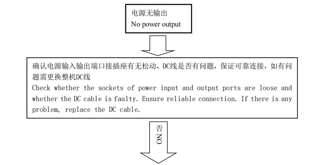
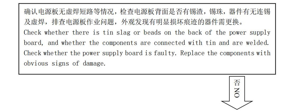
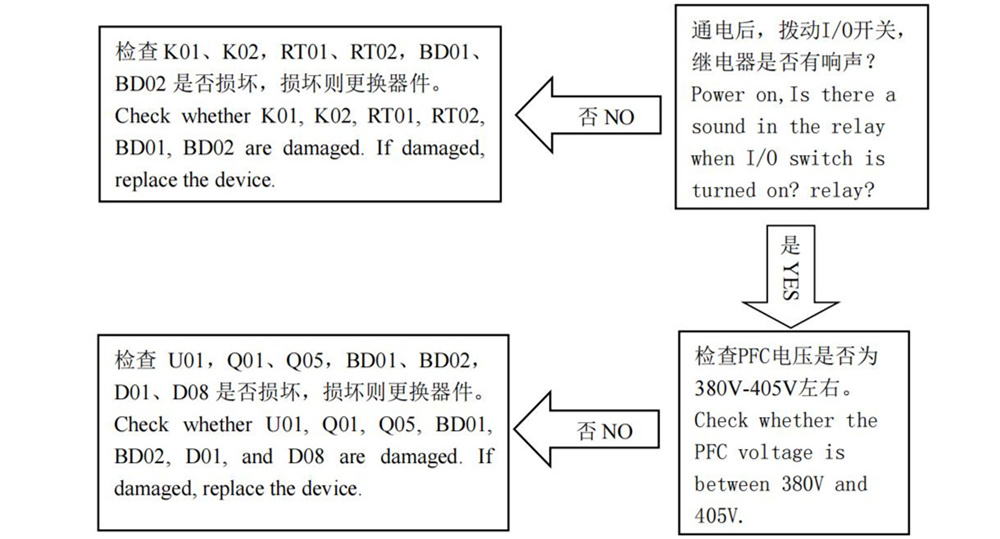


The maintenance method:
|
Bad phenomenon
|
Bad reasons
|
The maintenance method
|
|
No output
|
F01 open
|
Cause details: Overvoltage or overcurrent power supply is abnormal, Cause ac insurance
F01 to fuse.
Set the multimeter to diode gear and measure the L and N lines of the AC socket. If no
value is displayed, F01 is open. If there is a value, it indicates that the AC line is normal.
|
| No output |
High pressure BUCK small plate damaged |
Reason details: The high-pressure BUCK small plate is damaged due to the bad working
environment.
Maintenance method: Check whether the chips UF1, QF1, QF2, RF9, RF10, RF17, RF18,
RF19, RF14 are damaged or not. If there is damage, replace the components. |
| No output |
BD01 or BD02 is damaged
|
Reason details: The AC bridge rectifier diodes BD01 and BD02 are damaged due to excessive dust.
Maintenance method: replace BD01, BD02, F01, pay attention to replace the device
Cover the casing. The four pins of the bridge rectifier diode should cover
Sleeve, heat sink should be coated with thermal paste. |
| No output |
BD03 is damaged
|
Cause details: small bridge rectifier diode BD02 pin corrosion damage.
Maintenance method: replace BD03.
|
| No output |
Damage of fan |
PFC partial blast machine: check U01, Q01, Q05, BD01, BD02, D01, D08, Q02, Q07,
Q03, Q08, F01, D02, D09, and the peripheral patch resistance is damaged, if there is
damage, then replace the device.
Apply cooling cream when replacing BD01, BD02, Q01, Q05, D01 and D08, and cover
the heat shrink tubing when replacing F01.
When measuring whether the chip U01 is damaged, set the multimeter to the diode gear
to detect whether the VCC has a pressure difference of about 0.5V to the ground. If not,
replace U6: (IC: NCP1654).
——————————————————————————
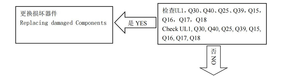
Main LLC part of the machine: check whether Q30, Q40, Q25, Q39, Q15, Q16, Q17,
Q18, UL1, R1, R2, R16, R18, D9, D12 is damaged, if damaged, replace the device.
When replacing Q1 and Q8, pay attention to applying heat dissipating cream.
When measuring whether the chip U2 is damaged, set the multimeter to the measuring
diode gear and detect whether there is a pressure difference of about 0.5V at both ends of
C94. If not, replace U2 (IC: NCP1399AM/1399AC).
|
| No output |
The synchronous rectifier is damaged
|
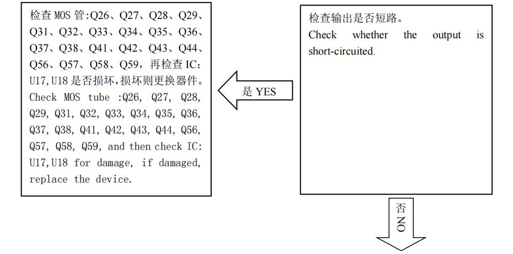
Cause details: Component/circuit corrosion leads to synchronous rectifier low voltage
MOS short circuit.
Maintenance method: Check Q26, Q27, Q28, Q29, Q31, Q32, Q33, Q34, Q35, Q36, Q37,
Q38, Q41, Q42, Q43, Q44, Q56, Q57, Q58, Q59, U17, U18, Q45, Q46, Q47, Q48, Q49,
Q50, Q52, Q7 5 and resistance 2R2 are damaged, if damaged, replace the device,
synchronous rectification MOS5 is 1 group, generally only one is broken, need to be
carefully detected.
Note: Apply heat sink cream again before replacing the heat sink of MOS tube lock.
|
| No output |
Auxiliary LLC2 small board damaged |
Reasons detailed: strong voltage breakdown auxiliary small board.
Maintenance method: Check Q16, Q11 for short circuit, if the above situation occurs,
replace the component. Check whether the VCC of the UL2 chip has a pressure difference
of about 0.5V to the grounding pin (pin 5). If not, replace the UL2 (IC model:
1399AM/1399AC).
Note: After replacement, reapply tri-proof paint.
|
Remark:
①Fan damage will cause the temperature of the power supply to rise too high, resulting in explosion, device damage
can be divided into two parts, PFC part of the explosion, LLC part of the explosion, analysis to each part of the
measurement.
②Replace the material must be corresponding to the model, do not think it is the same material by looking at the
same appearance.
2,Software failure
Analysis process and fault type determination:
a. If the power supply is cut off, remove it from the miner。
b. Short circuit the 2Pin on the right of the terminal (near the V+ terminal),As shown in figure:
c. The power monomer is powered on , not connected to the Miner.
d.Multimeter Set the DC voltage range and measure the output voltage of the power supply. (Connect the
positive terminal of the multimeter to the power supply terminal + and the negative terminal to the
power supply terminal -):
If < 11.9V, the power supply hardware failure is preliminarily determined, and the analysis process and
maintenance method are as described above.
If ≥11.9V, it is preliminarily determined that the power supply hardware is OK. Next, the power
supply connection performance is qualified for mining machine (qualified for computing power, power
consumption ratio and other indicators), and normal running aging;
If there is still no computing power, low computing power, abnormal PS data or other relevant error
codes, it is preliminarily judged as power supply software circuit failure;
If the aging calculation force and power consumption ratio are normal after connecting the mining
machine, it indicates that the power supply is OK.
The maintenance method:
Remove MCU small board STM8S005C6T6 IC chip and resistance container parts in turn, and replace
them accordingly.
Maintenance Precautions
When bad power supply is confirmed, be sure to use the protective switch to avoid explosion injury.
Pay attention to electrostatic protection during maintenance, and wear an antistatic bracelet.
Electric soldering iron temperature management, it is recommended to control in 380℃~420℃.
When replacing materials, use products of the same model and specifications. Do not use substitute
materials without permission.
The defective materials that are repaired and replaced shall be marked as defective, and the on-site
positioning management shall be optimized to avoid mixing with qualified products.
Record the power supply S/N serial number, bad phenomenon, bad reason, maintenance method and other
information, regularly provide maintenance record form.