Whatsminer M30 Series M31 Series Hash Board Repair Manual
By THANOS MINING
August 31st, 2022
Whatsminer M30 Series M31 Series Hash Board Repair Guide
Important reminder:
1. Repair the M30 series hash board, and the power supply range for the positive and negative poles of the hash board is 0.31~0.32V x number of layers (for example, 37 layers, 0.31x37=11.47, the power supply is 11.5v), it is recommended to test and maintain it according to the standard power supply.
2. During maintenance and measurement, the clock voltage should not be measured and judged with a multimeter. It is better to use an oscilloscope to measure and judge.
3. If the above 2 points are violated, it will lead to misjudgment, misplacement of accessories and unnecessary losses.
2. Construction of maintenance environment
1. Necessary tools for maintenance:
Necessary tools: electrostatic workbench, adjustable DC power supply (above 15A), 12V switching power supply, control board (for maintenance and testing), M1 chassis (with 1 fan), computer, 220V
Power cord, 12V power cord, network cable, flat cable.
Oscilloscope, Multimeter, Heating Station, Electric Batch/Phillips Screwdriver, Air Gun, Soldering Iron, Tweezers, Solder Paste/Solder Wire, Flux Paste, Change Knife
2. The method of fixture construction is the same as that of the M20 series, and the description will not be repeated here.
Important Note: Oscilloscopes Necessary for Repairing M3x Series Hashboards
3. Introduction to the Hashboard
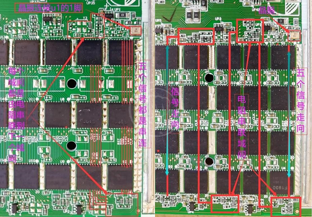
The working principle of M3x series and M20 series is roughly the same (please refer to the M20 maintenance guide for details). The M3x series hash board has only 1 crystal oscillator, and each layer of LDO provides 2 sets of 1.8v and 1 set of 0.8v power supply.
Total signal trend is as follows:
Note: CLK, RXD, RST are transmitted from u1 to the last chip, TXD is transmitted from the last chip to u1 to level conversion.
M31S:
 M30S:
M30S:
 All chips of the M30x series hash board have only 1 crystal oscillator, and each domain is connected in series to the next domain through a resistor.
M31s M30s
All chips of the M30x series hash board have only 1 crystal oscillator, and each domain is connected in series to the next domain through a resistor.
M31s M30s
 The 1.8v of each layer of LDO supplies power to pins 7, 8, 13, and 14 of each chip in each group, and 0.9v supplies power to pins 6 and 15 of each chip.
M31S M30S
The 1.8v of each layer of LDO supplies power to pins 7, 8, 13, and 14 of each chip in each group, and 0.9v supplies power to pins 6 and 15 of each chip.
M31S M30S
 17v boost circuit
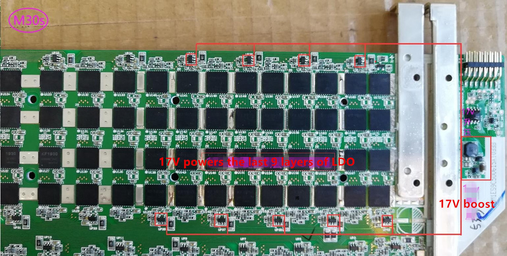
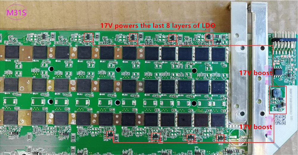 Tip: How many layers of power does 17v supply to the LDO, and finally the actual computing power board is the standard
Both the temperature sensor and the memory are powered by 3.3v
Tip: How many layers of power does 17v supply to the LDO, and finally the actual computing power board is the standard
Both the temperature sensor and the memory are powered by 3.3v
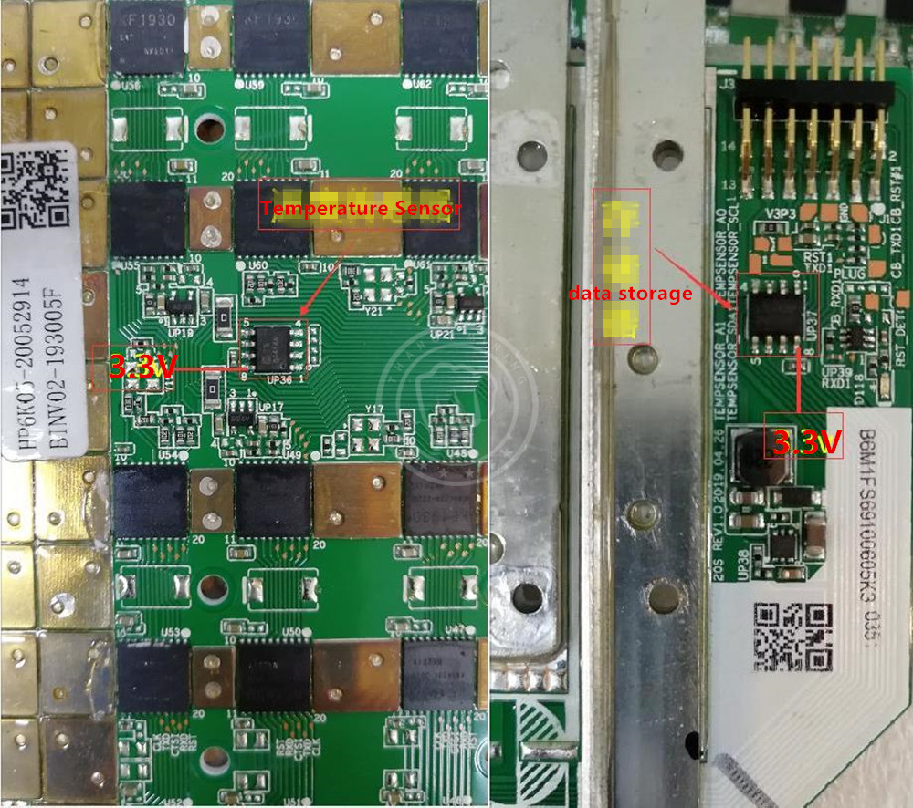 Level conversion is 3.3v, 1.8v conversion
 Fourth, the maintenance case:
Important note: To repair the M30 series hash board, first repair the RST signal, and then repair the CLK, RXD, TXD signals. It is important to remember that CLK must be measured with an oscilloscope. The inter-domain voltage of 0.15v is a normal voltage, and multiple error codes must be reported. log view log confirmation
Case 1: M31S reported 542 error code and could not read SM2 hash board:
Enter the IP display as shown below:
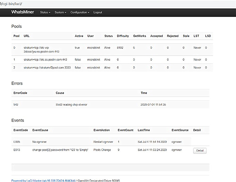 Remove SM2 and test it with a jig. The test result fails to reset (as shown in the figure below):
 Check according to the maintenance method, first repair and reset,
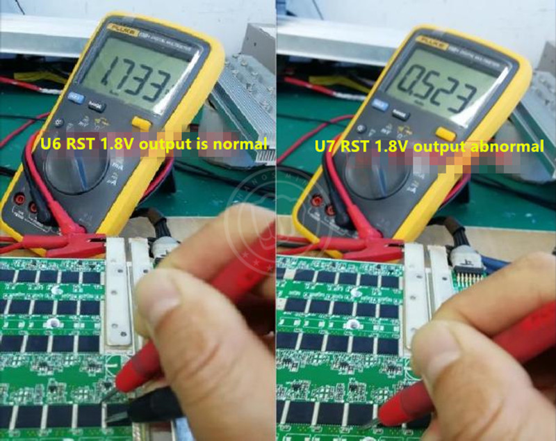
Enter the command echo 1 > /sys/class/gpio/gpio99/value in the test fixture interface, pull the reset level high, and measure the RST test points one by one to find that the u6 RST output has 1.8v, and the u7 RST has no 1.8v output, as shown in the figure below:
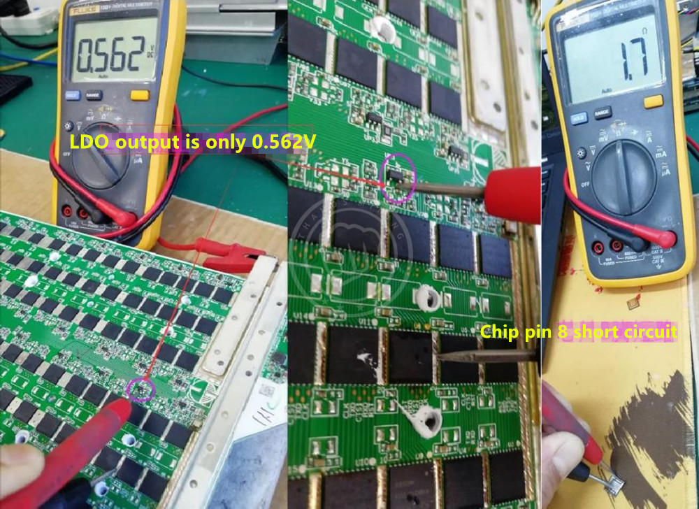
 The problem is basically determined at layer 3. Further measurement, it is found that the LDO output is only 0.56v,
Further measurement found that the 8th pin of u8 is only 1.7Ω, which is a short circuit, resulting in the LDO output voltage
insufficient.
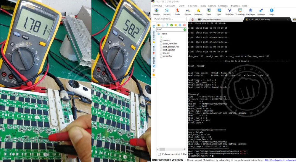
 Replace u8 chip, LDO output 1.8v is normal, LDO resistance to ground is 58Ω normal, fixture test result PASSD, as shown below:
 Case 2: M31s reports error 542 and cannot read SM2:
Enter the IP display as shown below:
 Remove the SM2 and test it with a jig. The test result shows that the chip is not fully read, and the u9 is missed as shown in the figure below:
 Remove the radiator of the hash board, directly replace the ninth chip, test OK, complete the installation and perform the aging test.
Note: When u9 is displayed, be sure to find the 9th chip in order, because the silk screen number and position number of some boards do not match.
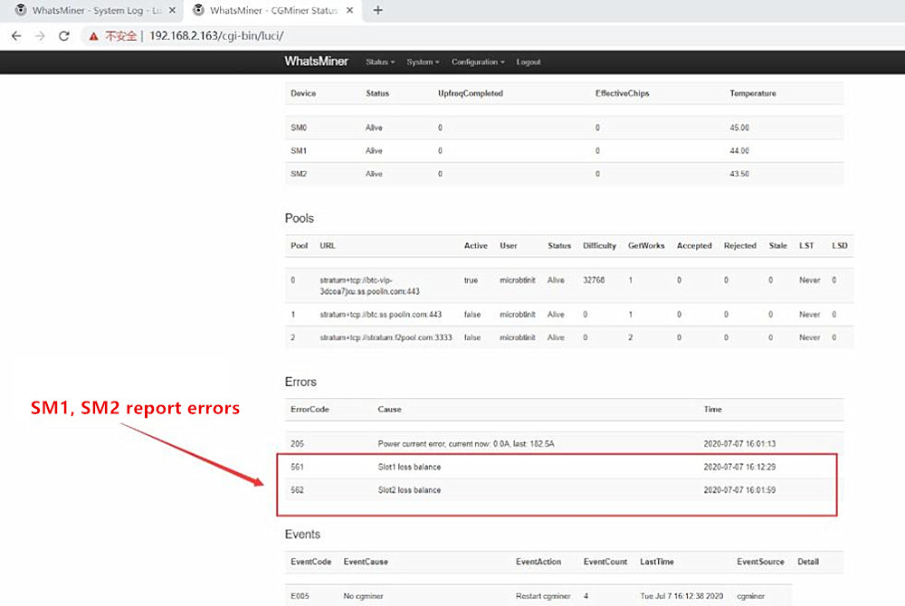
Case 3: M31S reports 561, 562 errors, SM1, SM2 read failure
Enter the IP display as shown below:
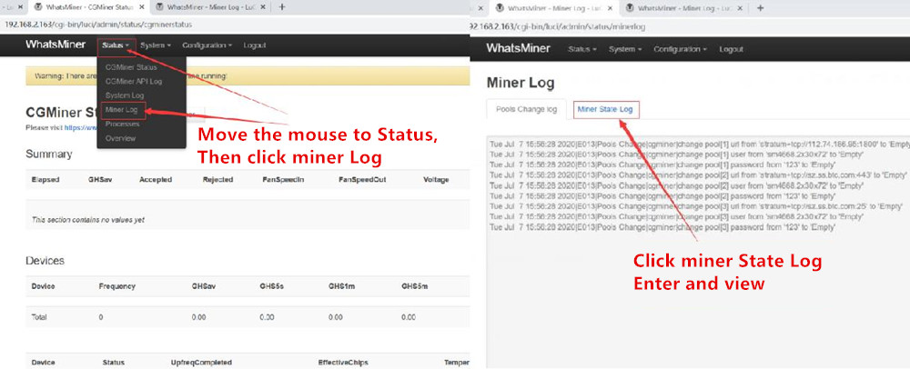
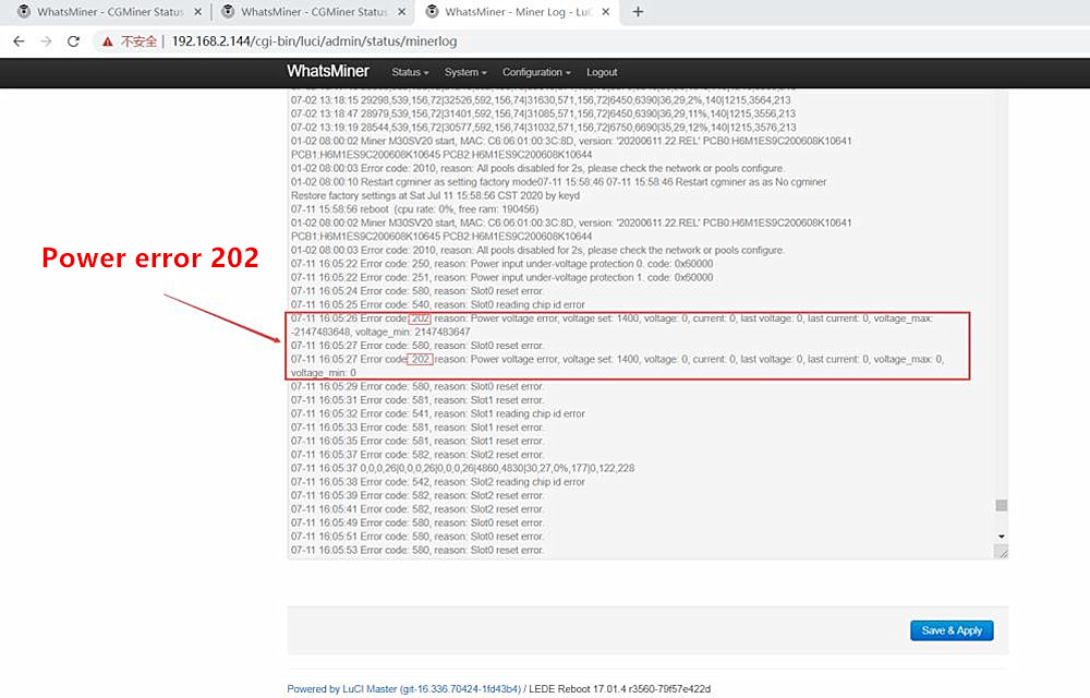
 After more than ten minutes of power-on observation, the machine will automatically restart, enter the Miner Log (Miner State Log) to check the log and find that the power supply causes the failure
The steps to view the log are as follows:
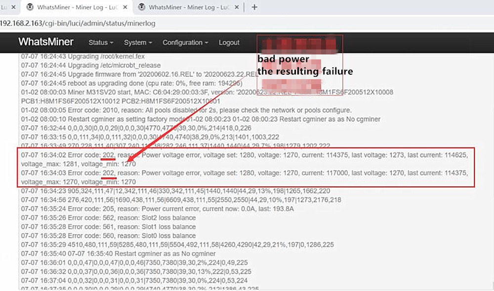 After comprehensive analysis, it is determined that 202 is reported as bad power supply, which causes the machine to run abnormally. Replace the power supply and test OK.
Case 4: M31S+ reports 540 error, SM0 chip is not fully read
Enter the IP display as shown below:
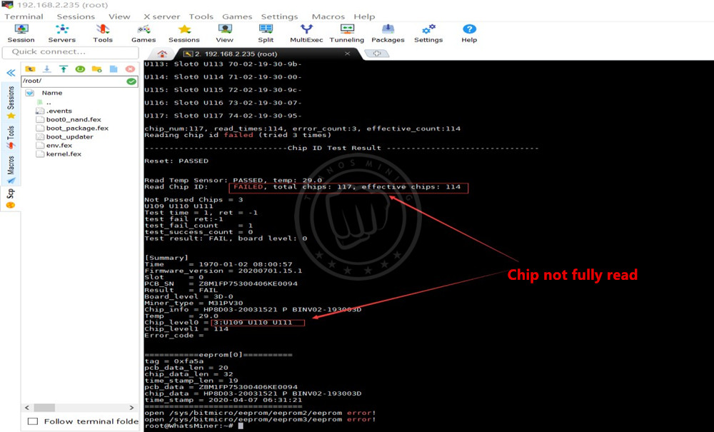
 Fixture test results u109, u110, u111 chips are not read, as shown below:
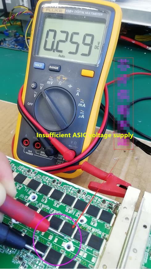
 Directly check this group of chips and find that the 1.8v power supply is insufficient. After careful inspection, it is found that the power supply pin of the u110 chip is shorted to ground (as shown in the figure below):
 Replace the u110 chip test OK, install the machine for aging test.
Case 5: M30S reports that the 530 SM0 board cannot be detected
Enter the IP display as shown below:
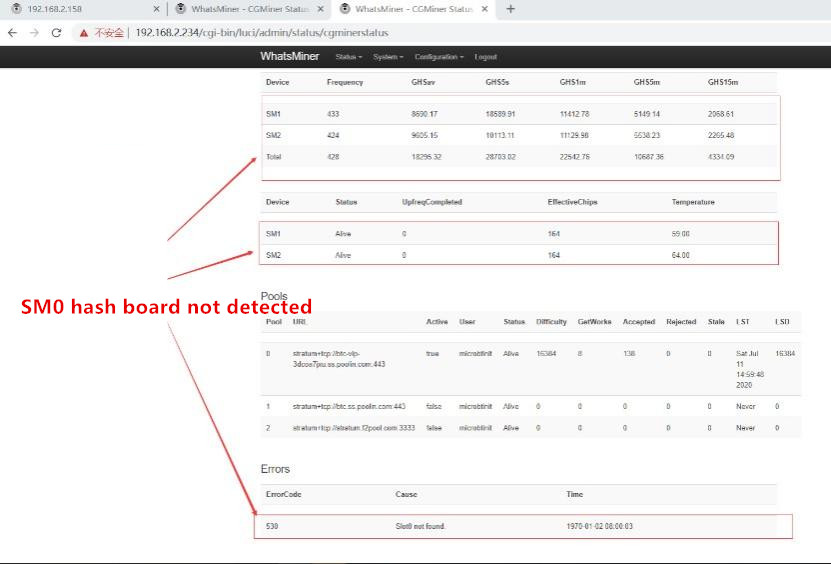 After careful inspection, it was found that the fan was damaged and vibrated, causing the cable to be loose, re-plug the cable, and power on the test OK.
Case 6: M30S reports 236, 255, 268, power error
Enter the IP display as shown below:
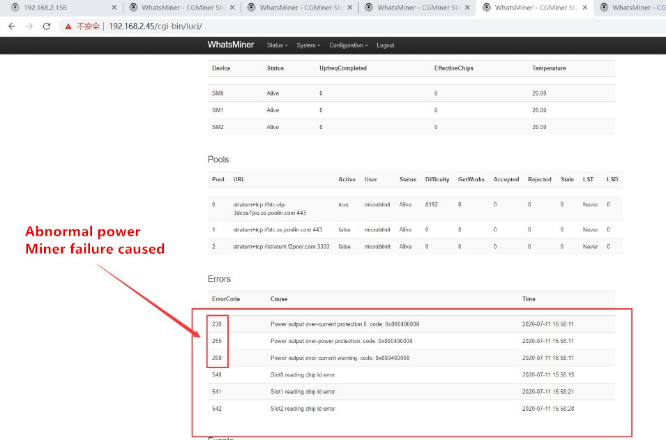 When such a power supply error occurs, it is caused by a bad power supply. Replace the power supply and the test runs normally.
Case 7: M30S reports 250, 251, 540, 541, 542 errors at the same time,
Enter the IP display as shown below:
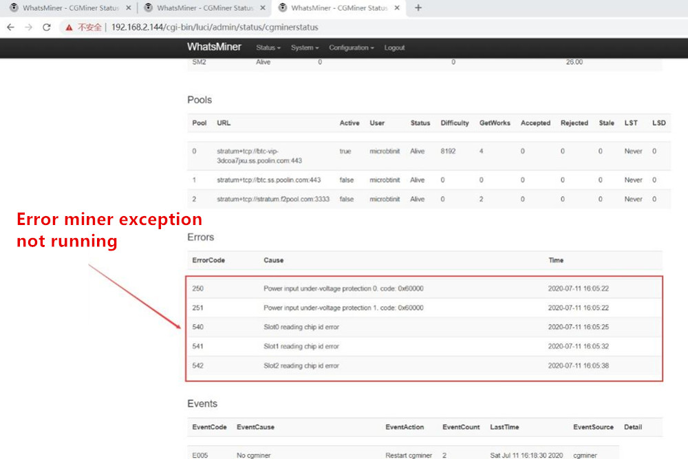 In the log, it is determined that the 202 error is caused by a bad power supply, replace the power supply, and the test is OK.
 Case 8: M30S+ reports errors 257, 540, 541, 542 (the analysis idea is the same as case 7)
Enter the IP display as shown below:
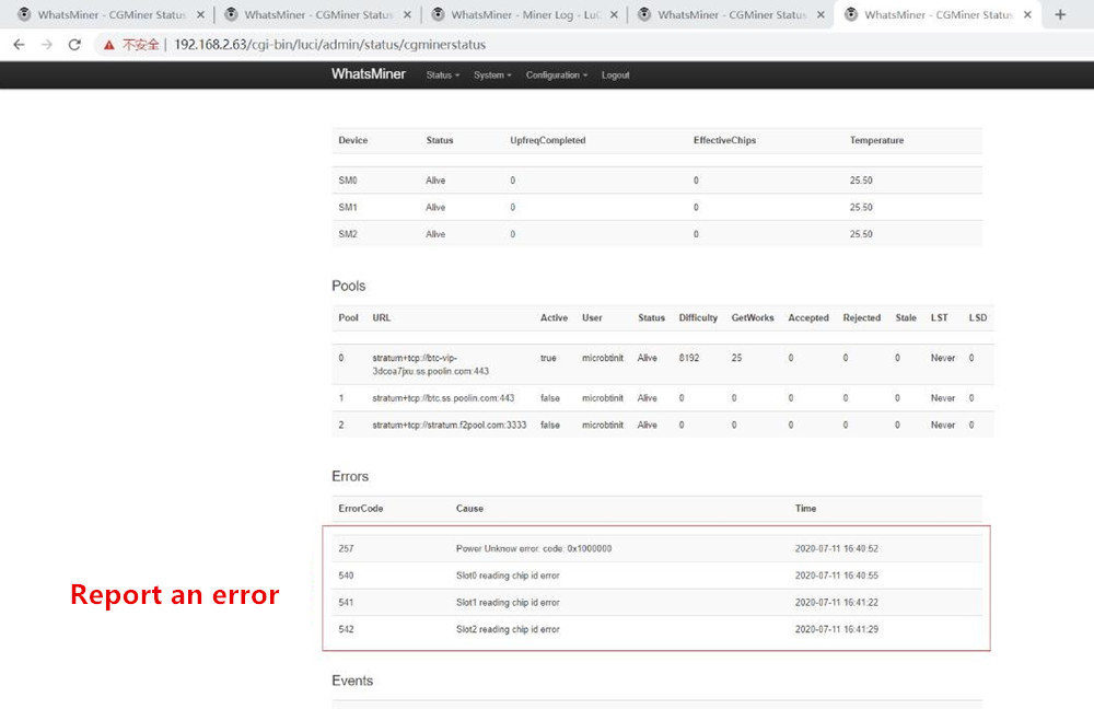 The progress is determined to enter the Miner Log (Miner State Log) to view the log
It is determined in the log that the 202 and 257 errors are caused by a bad power supply, replace the power supply, and test OK.


Previous
iPollo Miner Firmware And Tool
Read More
Next
Antminer/Whatsminer PSU Wake-up/Startup Tester Manual
Read More


 After more than ten minutes of power-on observation, the machine will automatically restart, enter the Miner Log (Miner State Log) to check the log and find that the power supply causes the failure


