Whatsminer M34S VE10 Repair Guide
By Thanosmining
August 30th, 2022
1. Overall structure
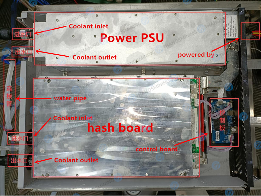
A machine is: a three-phase power supply, a computing power board and a control board. Both the power supply and the computing power board are equipped with a water-cooled radiator (as shown below)
 2. Water cooling board circuit description
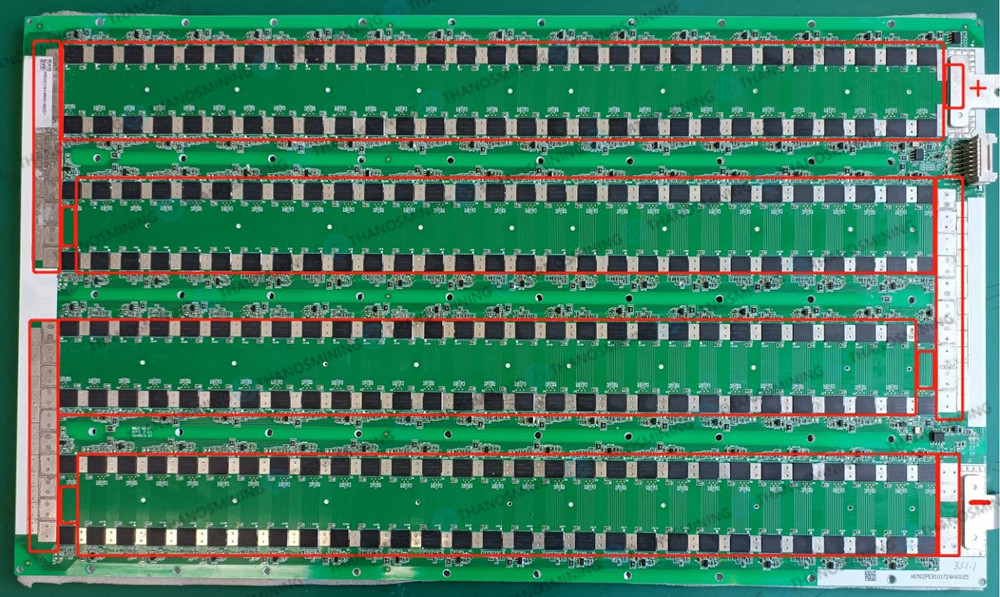
The board is 36v series powered (as shown below)
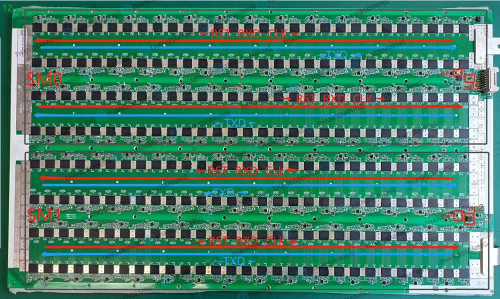
 1 piece of circuit board is composed of SM0 and SM1, SM0 signal RST, RXD, CLK (Y1) is transmitted from U1 to U116, U116 receives the signal, TXD is transmitted from U116 to U1 to UP3 to the control board.
SM0 signal RST, RXD, CLK (Y3) is transmitted from U117 to U232, U232 receives the signal, TXD is transmitted from U232 to U117 to UP2 to the control board.
 Troubleshooting and troubleshooting
| Fault phenomenon |
Reason |
Method of exclusion |
| Can't recognize hash board |
1. No 3.3v
2. Can't read eeprom |
1. Check the 3.3v circuit if there is a circuit
2. Check if uc2 is good |
| Can't read temperature sensor |
1. Poor power supply
2. Bad chip |
1. Check the 3.3v power supply circuit
2. Check if uc1 is good |
| Can't read chip/incomplete |
1. Poor RST signal
2. Bad CLK signal
3. Bad RXD signal
4. Bad TXD signal
5. LDO power supply is not good |
1. The RST signal interruption point is the fault location
2. The interruption point of the CLK signal is the fault location
3. RXD signal interruption point is the fault location
4. TXD signal interruption point is the fault location
5. The LDO signal interruption point is the fault location |
| Report high temperature |
1. Chip temperature is too high
2.UC1 reports high temperature |
1. Check whether the screws and thermal grease are well
2.Check whether the water temperature and water flow rate are up to standard |
| low computing power |
1. Poor power supply
2. A chip returns less nonce |
1. Check the output voltage of the power supply, if the voltage is low, replace the power supply
2. Which chip has a low nonce to replace which chip |
 When installing a heat sink on a circuit board, every screw must be done, otherwise it may cause uneven pressure on the heat sink, causing localized high temperatures.
 Test line connection precautions
The ground wire of the AC input of the test instrument cannot be connected to the ground wire of the AC input of the DC power supp.
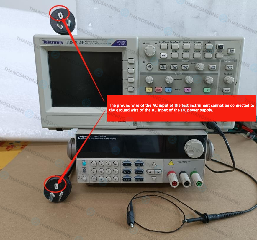 The test instrument and the negative pole of the DC power supply cannot be connected together.
 Soldering the chip must heat the entire circuit board evenly, and then locally heat the part that needs to be soldered.
 The above are the precautions and signal directions when repairing this model.
Other maintenance ideas and techniques are consistent with the models related to the KF1930 chip.

Previous
Whatsminer M30 Series M31 Series Hash Board Repair Manual
Read More
Next
Antminer/Whatsminer PSU Wake-up/Startup Tester Manual
Read More


