Bitmain APW9/APW9+ Power Supply Repair Manual
By THANOS MINING
January 25th, 2020
APW9 APW9+ is a special power supply for mining machines produced by Bitmain, which is suitable for a variety of Antminer models.
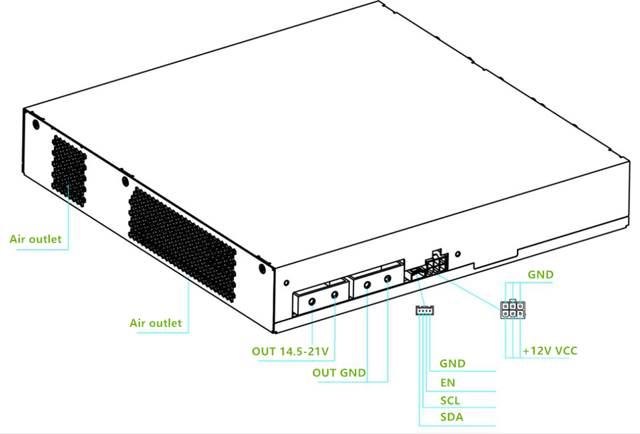
APW9/APW9+ consists of 1 large board, 3 fans and a lower case. Under normal circumstances, the two input channels are connected to AC220V, and there are two DC output voltages, which are SB 12V, and the main voltage output is 14.5V-21V. PIC port and mining machine communication control.
 Feature:
14.5V-21V voltage adjustable output, the maximum current can reach 170A;
12V voltage fixed output, current up to 12A.
200-240V wide voltage input
Internal under voltage, short circuit, overload, over temperature protection.
Common fault maintenance ideas and cases:
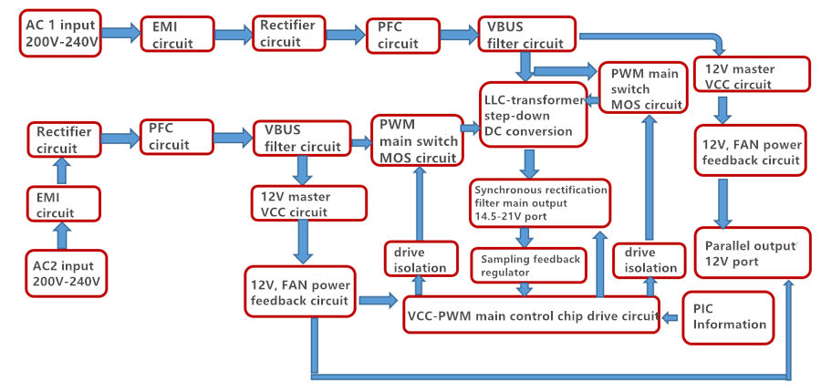
1-Block diagram of the basic principle of the power supply
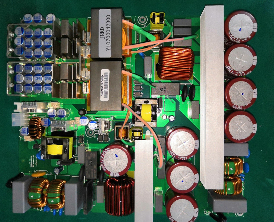
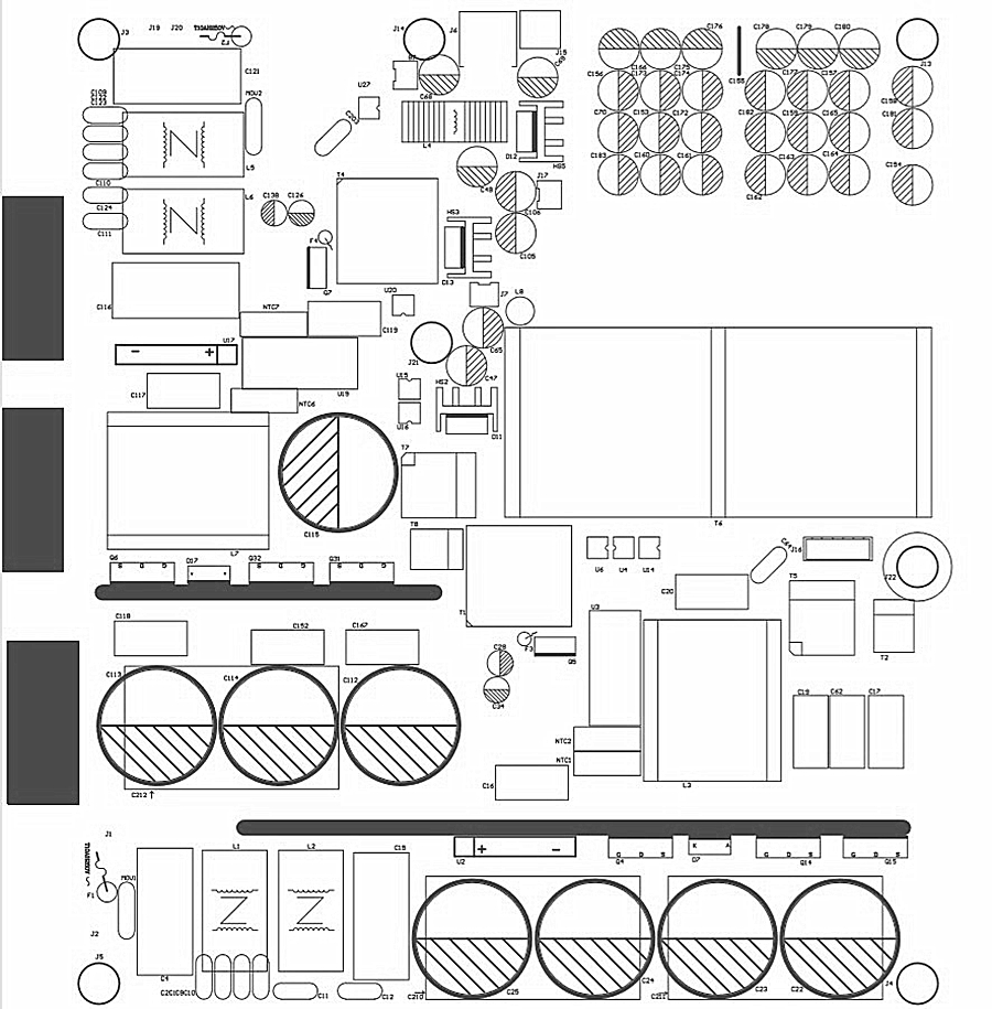
 Power PCBA board layout:
1A---The first AC input and EMI circuit,
1B--PFC and main shunt MOS circuit,
1C---12V auxiliary and VCC circuit.
2A---The second AC input and EMI circuit,
2B---PFC and main and parallel MOS circuit,
2C---12V auxiliary and VCC circuit,
2D--12V output port and PIC communication port
 The picture of the plug-in surface, there will be small differences in different versions, but the principle is similar.
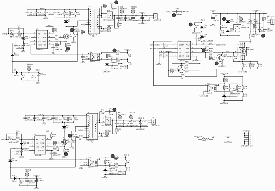
 2 groups of AC input EMI to PFC circuit schematic diagram, such as AC 1 channel key measurement F1 fuse, U2 rectifier bridge, Q4, D7, D5, D6 is damaged (the other channel is the same as the inspection method). Note that when the MOS is damaged, the drive resistor and circuit may be damaged simultaneously and need to be replaced. During normal operation, it can be judged that the DC voltage at both ends of the large capacitor is 410-420V.
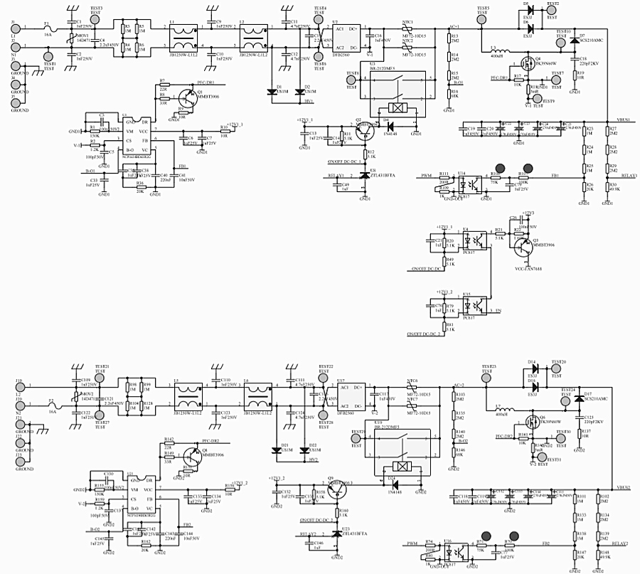 2 groups of 12V auxiliary circuit and fan power supply principle,
For example, 12V 1 channel, first measure the voltage detection startup resistance R33, 47K, connect the high voltage to D1, D2,Whether F3, Q5, D8, D9, T1 are damaged, etc. (same for other inspection methods).
12V output, the following circuit consists of two front-end 12V series, the final control is converted to output +12V, and then powers the Miner machine control board.
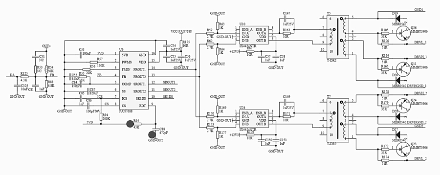
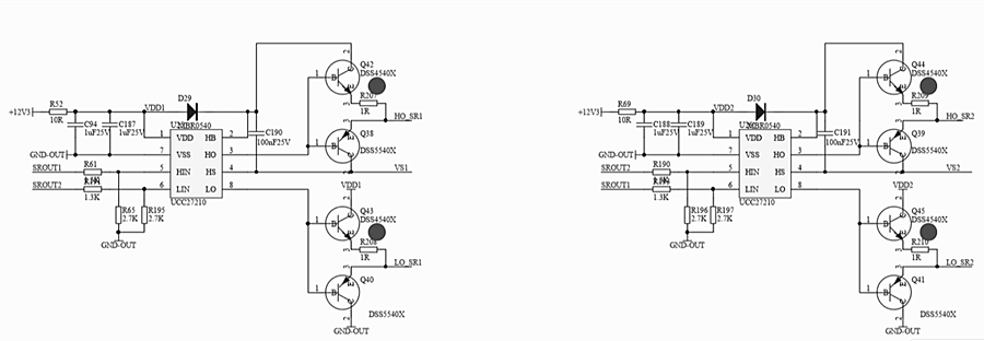
 Main control PWM drive circuit, PIC control voltage regulation schematic diagram, focus on measuring the main IC VCC power supply and drive transformer.
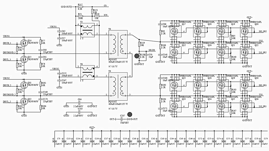
 LLC circuit two-way main switch MOS and transformer conversion step-down synchronous rectification DC filter output circuit, focusing on testing main switch MOS Q14; Q15; Q31; Q32, whether the positive and negative poles of the output rectifier MOS are short-circuited, overcurrent protection Circuit transformers, etc.
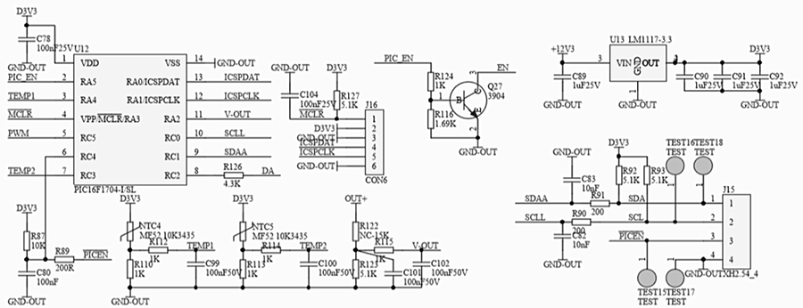
 PIC control circuit, J15 communication and programming port.
 SMD patch A side and plug-in B side device position silk screen.
 SDM patch location map.
 Repair steps:
1. Check whether the appearance of the power supply is seriously damaged or deformed, and whether the DC fan and AC socket are damaged.
2. Turn on the AC220V power supply, check whether the fan rotates normally, and use a multimeter to check whether the voltage of the output J6 terminal is 12V (12.1V-12.50) to eliminate false detection.
3. Open the case to check whether the components and solder surface are burnt (the key point is whether D1, D2, D21, D22 are damaged, and whether the 12V circuit chip capacitor has sparks), and use a multimeter to check whether the F1 fuse at the AC input end is disconnected. U2 rectifier bridge; PFC MOS Q4; D7; D5; D6 is short-circuited (other methods are the same as inspection methods), measure the main switch MOS Q31; Q32; Q15; Q16 and output patch MOS Q17; Q18; Q19; Q20; There is a short circuit, if there is a short circuit, check the position of the replacement component, pay attention to the circuit resistance around the bad MOS tube; the triode may be damaged and needs to be replaced.
4. Check whether there are other components in the auxiliary 12V circuit F3 and U5; T1; Q5; D8, D9 are short-circuited or open and the surrounding components are burnt, etc., and replace if necessary.
5. If there is no abnormality in the above positions, the F1 or F2 fuse path is normal, the DC fan rotates after the two-way AC power is energized (if there is no rotation, measure whether the fan socket has 12V, if the replacement fan is normal), the output terminal J6 has 12V voltage, measure Whether there is DC410V-420V at both ends of the bidirectional PFC large capacitor TEST20-TEST30 or TEST2-TEST7, otherwise check the PFC chip U21 or U1, pin 7. If there is no abnormality, check the PWM circuit U9; U10; U24; the power supply VCC has 12V voltage or judge whether the material is damaged and replace it, and whether the T5 or T7 drive transformer is damaged.
6. Other defects need to be further analyzed and judged according to the skills of maintenance personnel.
After the above inspection is completed, the DC output of the single power supply test main circuit needs to be short-circuited with J15 PIN pins 4-5 to output about DC21.3V, as shown by the EN-GND pin. Note that the wrong short circuit may damage the chip, and the AC220V test can only be performed after replacing the faulty device and checking that the soldering is correct. Note: If other circuits check the normal large capacitor with 420V, if there is no output after short circuit, it can also be judged that the PIC chip U12 firmware is reprogrammed or the IC is replaced (generally there are fewer defects here).

Previous
Bitmain APW7 Power Supply Repair Manual
Read More
Next
Antminer/Whatsminer PSU Wake-up/Startup Tester Manual
Read More


