Bitmain APW7 Power Supply Repair Manual
By THANOS MINING
January 10th, 2020
 APW7 is a high-efficiency DC power supply produced by Bitmain, with single-phase AC input, single-channel DC 12V output, and a power of 1800W.
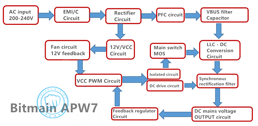
With 200-264V wide voltage input characteristics, the power factor is greater than 0.99 (full load). The highest conversion rate is up to 95% with 1% output ripple.
There are undervoltage, short circuit, overload, high temperature protection.
——————————————————
Principle overview diagram:
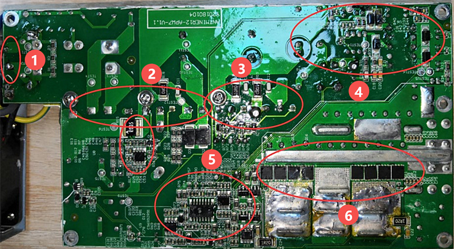
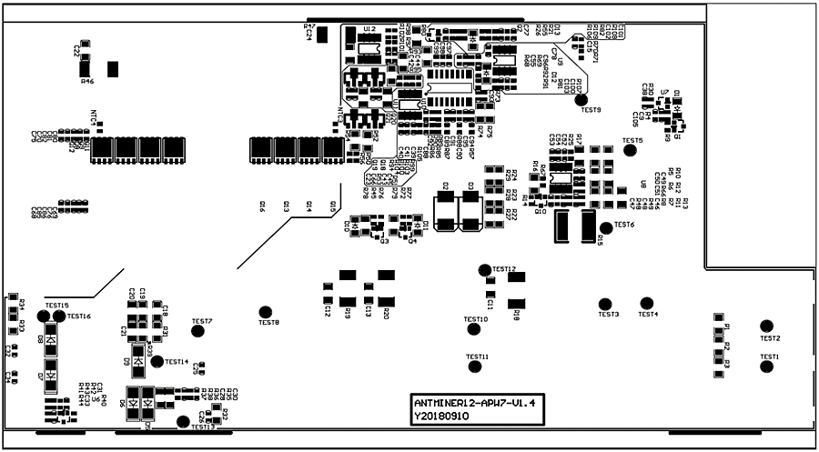
 PCBA circuit board layout:
1- Input F1 fuse
2- Rectifier bridge PFC driver, main Q circuit
3- LLC main switch circuit
4- Auxiliary power supply circuit, providing VCC power supply
5- PWM drive and detection feedback protection circuit
6- Main output circuit MOS
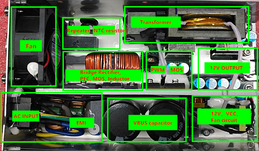
 DIP plug-in panel layout:
 Schematic diagram of side A of SMD patch:
 Plug-in B side position silk screen:

————————————————————
Troubleshooting:
The fan does not turn, and there is no voltage output.
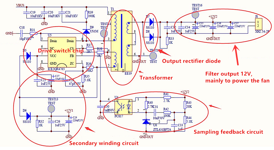
The schematic diagram of the auxiliary circuit,
if there is no 12V2 voltage, the fan will not turn, focus on testing the voltage to detect whether the pins 3 and 4 of the startup chip U5 are short-circuited.
Whether the R37, R38 resistors are damaged.
And whether T1 (winding cable) is disconnected. D5, D6, D7, D8, D9 and fans are damaged. And check the voltage regulator feedback circuit.
————————————————————
Troubleshooting:
Low fan speed, no voltage output.
Schematic diagram of the main control PWM drive circuit,
Focus on checking whether the chip U10, VCC 12V power supply is normal, and whether U11, U12 and the drive transformer T4 are damaged.

————————————————————
Troubleshooting:
Do not turn on, turn off for a short time after turning on.
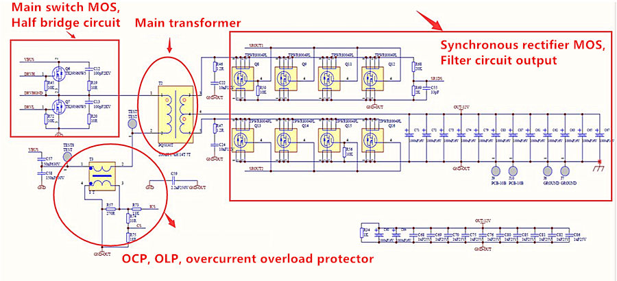
First check whether the fuse is disconnected, the main switch MOS and the transformer convert the step-down synchronous rectifier circuit,
Focus on testing the main switch MOS Q6, the output rectifier NMOS, Q14, Q16, Q15, Q13, Q8, Q9, Q11, Q12, and whether the positive and negative poles are short-circuited.
 1. Check whether the appearance of the power supply is seriously damaged or deformed, and whether the DC fan and AC socket are damaged.
2. Power on the AC220V to check whether the fan rotates normally, and check whether the output J6 terminal voltage is 12V (12.1V-12.50) with a multimeter to eliminate errors.
3. Open the case to check whether the components and the solder surface are burnt or not (the key point is whether the R33 resistor is damaged), use a multimeter to check whether the F1 fuse at the AC input is open, and whether the U2 rectifier bridge; PFCMOS Q1; D7; D5; D6 whether there is a short circuit,
Measure the main switch MOS Q6;Q14;Q15;Q16 of the PWM circuit and the SMD MOS Q17;Q18;Q19;Q20;
If there is a short circuit, it is necessary to check and replace the component position, and pay attention to the circuit resistance around the bad MOS tube; the triode may be damaged and needs to be replaced.
4. Check whether the auxiliary 12V circuit U5; T1; Q5; D11 is short-circuited or open-circuited and the surrounding components are burnt, etc., if necessary, replace it.
5. If there is no abnormality in the above positions, the F1 fuse path is normal, and the DC fan rotates after the AC is powered on (if there is no rotation, measure whether the fan socket has 12V, if the fan is replaced normally), the output terminal J6 has 12V voltage, and measure the PFC large capacitance Whether there is DC370V-380V at both ends of C16 or C17, otherwise check U1, pin 7 VCC power supply has 12V or judge that the material is damaged and replace, if there is no abnormality, check the PWM circuit U9; U10; U11; power supply VCC has 12V voltage or judge that the material is damaged and replace , and whether the T4 drive transformer is damaged,
————————————————————
Tips:
PSU maintenance is different from a hash board. The faults involve a wide range and are not easy to troubleshoot. Other defects require further analysis and judgment based on the skills and knowledge of the maintenance personnel.

Previous
Antminer Control board Repair Manual
Read More
Next
Antminer/Whatsminer PSU Wake-up/Startup Tester Manual
Read More


