Antminer Control board Repair Manual
By THANOS MINING
January 9th, 2020
Antminer Control board has good compatibility, so most new miners use this control board, which adopts 7Z007S main control scheme. Suitable for S17 series, T17 series, S19 series. Its main layout is as follows:
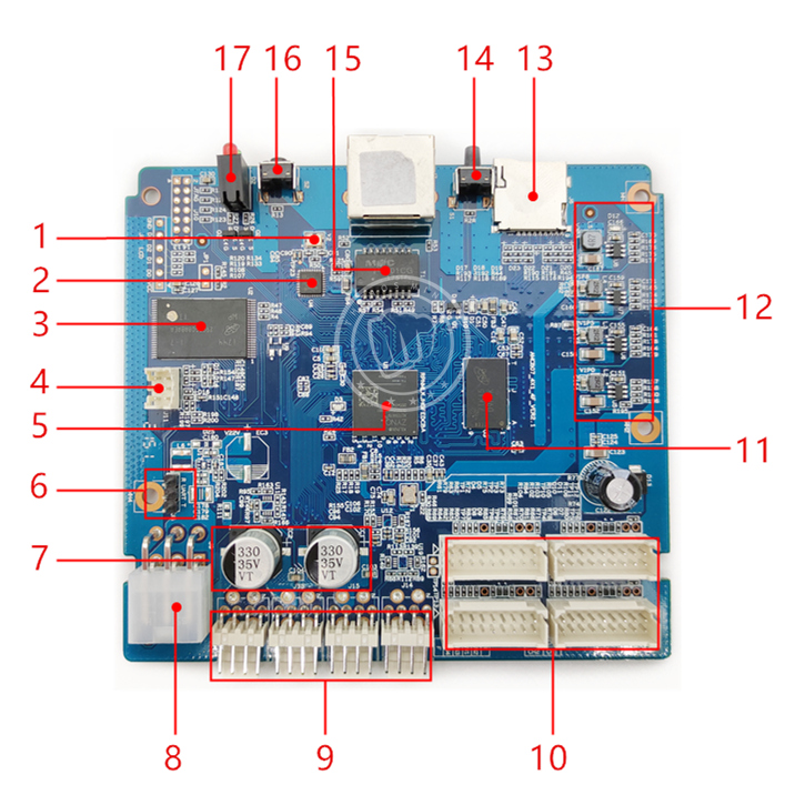 1,25Hz crystal oscillator
2,Ethernet transceiver
3,Flash
4,4pin PSU data interface
5,Main control chip CPU
6,External data interface
7,Filter capacitor
8,6pin power interface
9,Fan interface*4
10,IO data interface*4
11,DDR
12,Power control part
13,SD card slot
14,IP button
15,Ethernet transformer
16,Reset button
17,Indicator light
————————————————————
Troubleshooting:
1. When the whole control board is not turned on, no voltage or low voltage, it is necessary to judge whether the power supply is faulty.
As shown in the figure below, to measure the power module, the sequence should be 3.3V, 1.8V, 1.5V, 1.0V. If abnormal, check for damaged parts in this area (area 12).
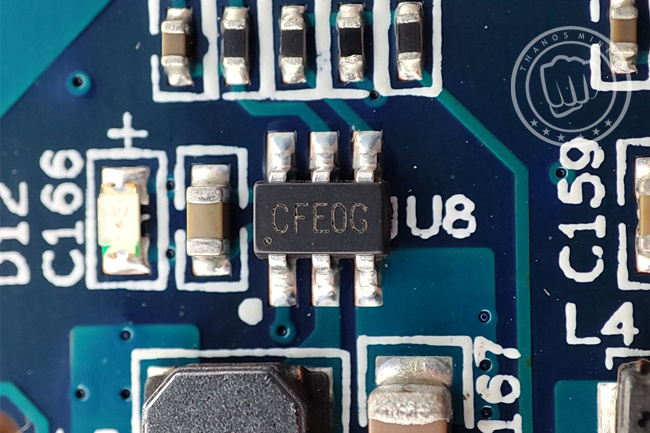
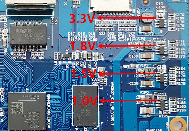 3.3V is the front end voltage. If there is a short, remove U8 before testing. If it is still short circuit, you need to remove the CPU and test again (because it may be caused by damage to the CPU).
Other 1.8V, 1.5V, 1.0V are abnormal, just replace the corresponding voltage conversion IC.
 Damaged CPU or poor solder can also cause a 3.3V short circuit, or the control board cannot be turned on. Please reheat and repair the CPU first, and then test after cooling down. If the fault persists, the CPU needs to be replaced.
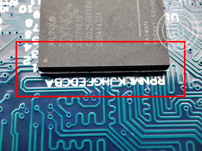 By the way, check the circuit on the back of the CPU for damage.
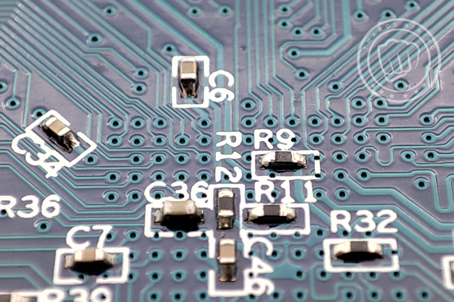 If the voltage is normal and the onboard indicator is not on, please check whether the 25Hz crystal oscillator (area 1) is in good condition. If the component is damaged, the control board voltage is normal, but it can't work, can't read the IP, only the DDR light will blink.
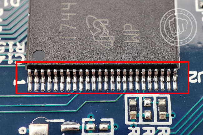
 If the voltage is normal, the DDR indicator is normal, but the external indicator is always red, you need to check the Flash or CPU.
Re-solder the Flash pins, or check whether the CPU is hot, you can press the CPU with insulating paper and test at the same time.
 ————————————————————
Troubleshooting:
2. The hash board is not fully extracted and the chain is dropped.
First, please replace the IO data cable and test it. If the fault persists, please check the electronic components of the IO data interface of the control board.
 ————————————————————
Troubleshooting:
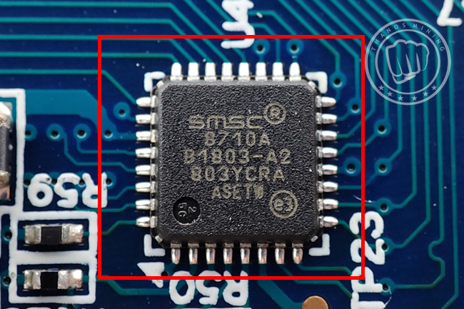
3. The network indicator light is off and IP cannot be provided.
Please check the network transformer (area 15) for bad soldering, re-solder and test. If the fault persists, replace the element. If the fault persists after replacement.
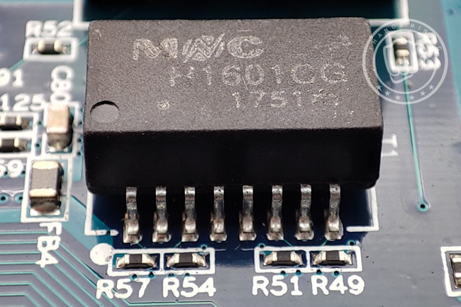 If the fault persists after replacement, the Ethernet transceiver IC (area 2) needs to be checked.
 —————————————————————
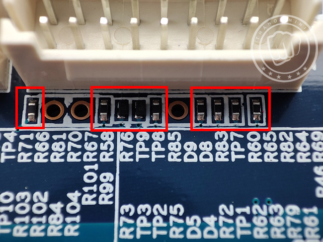
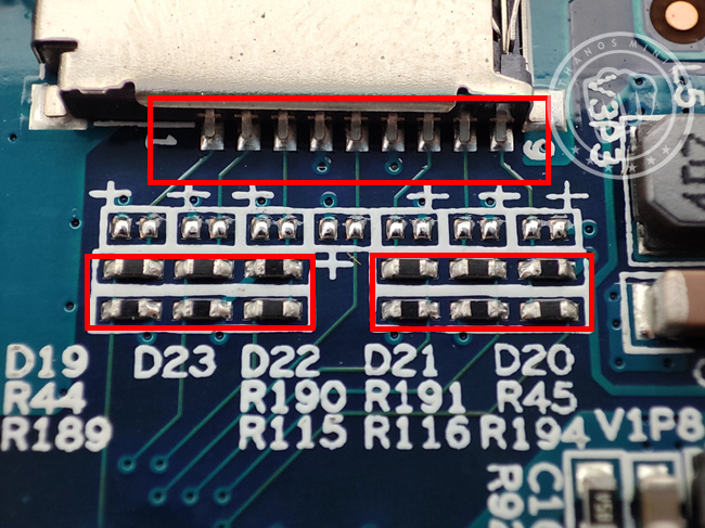
Troubleshooting:
Can not use SD card to upgrade, please check the card slot and rear resistance.
 Tips:
Tips:
The above is an overview of the vulnerable components of the Antminer control board. Among them, the probability of CPU damage is greater. If you have an unused control board, keep it away from static electricity.

Previous
Antminer hash board PIC file burning tutorial
Read More
Next
Miner Fan Speed Meter User Manual
Read More


