Avalon Test Fixture Manual For Canaan AvalonMiner A8 A9 A10 Series
By THANOS MINING
April 30th, 2022
 This article was written by Thanosmining, please indicate the original author when reprinting. Misappropriation or use for commercial purposes is prohibited without the permission of the company.
Avalon test fixture, 320X version, supports the test of the following models:
This article was written by Thanosmining, please indicate the original author when reprinting. Misappropriation or use for commercial purposes is prohibited without the permission of the company.
Avalon test fixture, 320X version, supports the test of the following models:
Canaan Avalon A8 series: A821/A841/A851/A852
Canaan Avalon A9 series: A910/A911/A920/A921/A910/A911
Canaan Avalon A10 series: A1066 A1041 A1046 A1047
Before using this test fixture, please read the following introduction carefully. Improper operation can easily damage the test fixture and hash board.
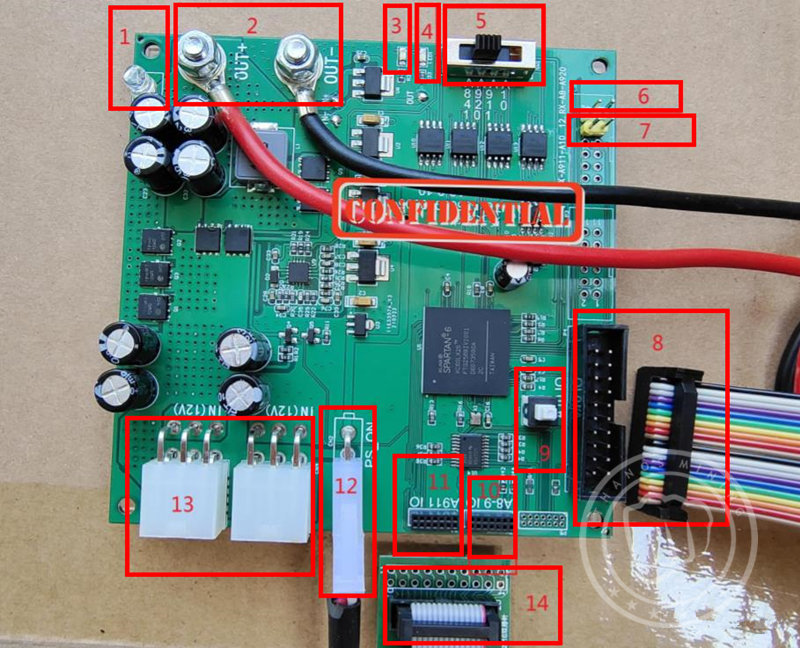
Test fixture device and layout description:
 1.
1.
White LED light: Indicates whether the main output is powered or not. When it is on, it means there is power, and when it is off, the main output has no voltage.
2.
OUT+ (red clip): the main output positive pole, the voltage is divided into 10V and 12V, the output voltage is controlled by the model switch. A8 series and A9 series are 10V, A10 series is 12V, before connecting the alligator clip to the hash board, be sure to confirm whether the hash board model and model switch are correct.
OUT-(black clip): Main output negative pole.
3.
LED2 (green LED): Indicates that the Hash board has passed the test and does not require maintenance.
4.
LED1 (red LED): Indicates that the board is not well tested and needs to be repaired; the specific reason needs to check the test result LOG, and some problems can be ignored.
5.
Model switch: a total of 4 modes, the main output voltage is controlled by this switch,
The models are:
① A841: A821/A841/A851/A852
② A920:A920/A921
③ A911:A910/A911
④ A10: A1066 A1041 A1046 A1047 series (Do not support Pro)
The models listed above may not be complete, but many are generic.
6.
White 2PIN interface, serial output of mode ① and mode ②,
Pin 11 is GND and pin 12 is RX.
7.
Yellow 2PIN interface, serial output of mode ③ and mode ④,
Pin 9 is GND and pin 10 is RX.
8.
A10 series IO connector: A10* data cable interface, used to connect to the data IO interface of the A10 series hash board.
9.
Self-locking switch: Press this switch when you want to maintain and check the signal, the board signal (for example, the C signal will have a high level of one chip and a low level of the chip) will be output regularly, which will be more convenient when measuring signals;
When testing the hash board normally, this switch needs to be reset, otherwise there will be no output from the serial port (that is, no display on the computer screen).
10.
A8 series, A92 series IO data connector, data line interface of mode ① and mode ②, connected to the data interface of Hash board of A8 series-A920/A921 through the adapter board.
11.
A911 IO: The three-speed data cable interface is connected to the A910/A911 hash board data cable interface through the adapter board.
12.
PS_ON: Connected to the foot switch, press it to supply power immediately, release it to power off immediately. It is recommended that the continuous pressing time does not exceed 3 seconds. When the continuous pressing reaches 6 seconds, the fixture will also automatically power off to prevent the hash board from overheating. If you want to cancel the automatic power off function, you can remove the part U7.
13.
IN(12V): The 12V output from the PC power supply is connected here to supply power to the test fixture. Due to the large current, the two must be connected to two interfaces at the same time.
14.
Adapter board: A8*-A9* cable universal adapter board, connected to the test fixture, and connected to the Hash board via 2*7 cables.
——————————
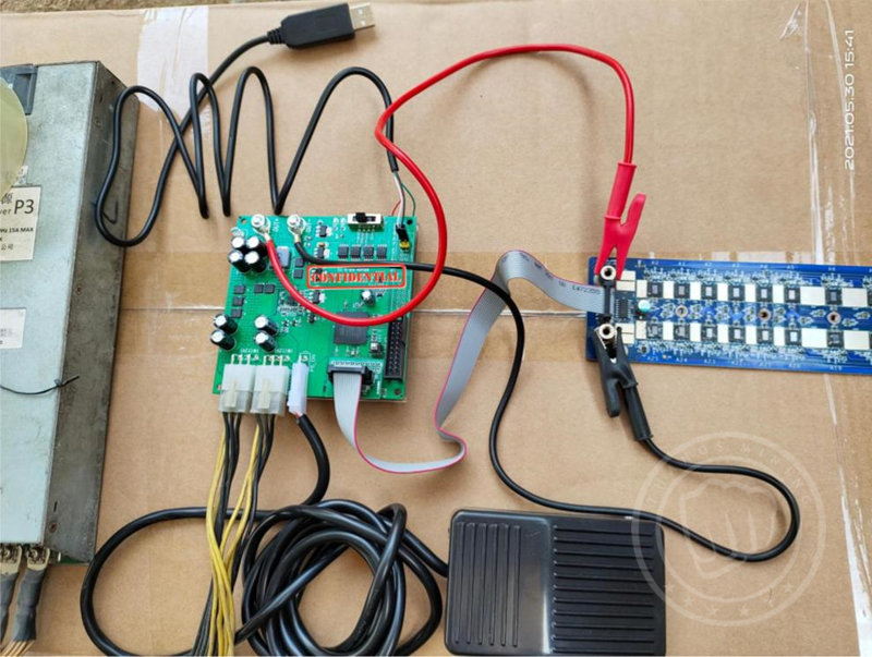
Test steps:
1. Connect the USB to serial port to the computer, and the fixture end is connected to the white or yellow interface according to the gear.
2. Open the software (CH341 serial port driver.EXE) to install the serial port driver; if it is already installed, you can ignore this step.
3. Open the serial port software (serial port software.exe), select the corresponding COM* for the serial port number (you can view the serial port number in the device manager), select 115200 for the baud rate, and select Open the serial port.
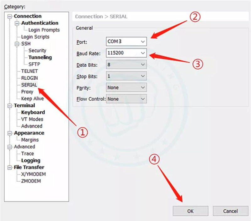 If you have not used serial port software before, you can refer to our tutorial:
XSHELL 5/6/7 Configuration Tutorial (Test Fixture Software Program)
4. Turn the switch to the corresponding position according to the model.
If you have not used serial port software before, you can refer to our tutorial:
XSHELL 5/6/7 Configuration Tutorial (Test Fixture Software Program)
4. Turn the switch to the corresponding position according to the model.
5. Connect 2 6PIN header outputs on the PC side to the fixture input.
6. Connect the foot switch interface to PS_ON, put the switch on the ground, and use the foot to control the power supply later
7. Connect the cable to the fixture according to the model.
8. Connect the main output power supply to the main power supply of the hash board, connect - first and then +.
9. Connect the cable to the cable interface of the hash board. (According to experience, this step must be connected before stepping on the power) 10. Step on the foot switch, the test result will be displayed in 2 seconds, one red/green LED will light up, and there will also be a Log display on the serial port software, and the test result will be displayed. Then release the foot switch (it is recommended that the continuous pressing time does not exceed 3 seconds. When the continuous pressing time reaches 6 seconds, the fixture will automatically power off to prevent the hash board from overheating).
The following is a schematic diagram of the Hash board connection:
A920 access
 A1066 access
 Important hint:
The following problems can easily lead to damage to the test fixture:
1. The mode switch must select the correct model.
2. The connection between the test fixture and the Hash board must be correct, and cannot be misplaced or reversed.
3. The hash board cannot have abnormal short circuit,
The main power supply can be measured with a multimeter:
Whether the resistance values of the 6 data signals (DI, RI, CI, DO, RO.CO) of the A10 series data interface are normal.
A8-9: Whether the resistance values of the 6 data signals (DI, RI, CI, DO, RO.CO) and 2 power supplies (1.8V, 12V) of the data interface are normal.
Wrong connection and abnormal short circuit of the hash board can easily damage the test fixture or the hash board, please be sure to follow the precautions mentioned in this article!

Previous
Innosilicon and Aladdin Miner Portable Test Fixture User Manual
Read More
Next
Antminer/Whatsminer PSU Wake-up/Startup Tester Manual
Read More


