PicoBT Tester User Manual
By THANOS MINING
September 12th, 2022
PicoBT Tester User Manual
The device has a powerful multi-mode function that can help you do more maintenance work. Currently supports more than 70 kinds of hash board tests and digital power tests, as well as eeprom editing.
Firmware upgrades will be carried out irregularly in the later period to adapt to more new models.
This article describes how to use the device and related functions:
(The article is published by ThanosMining authorized by PicoBT. Without permission, reproduction and modification are prohibited)
1.Ports Of Tester
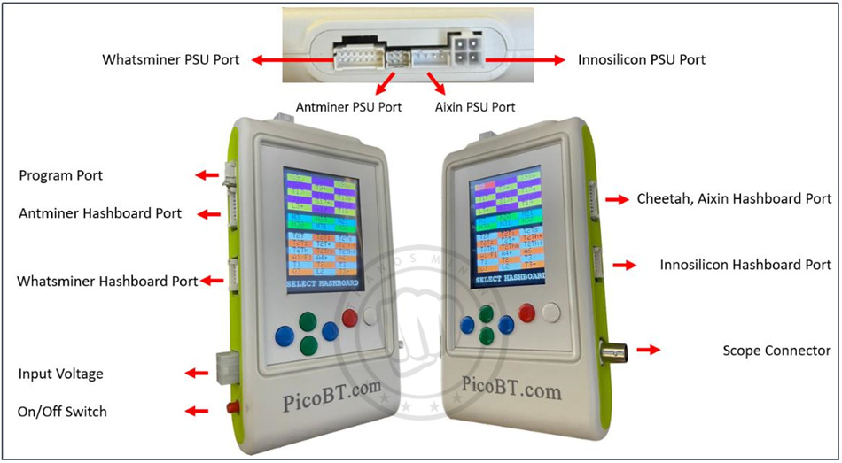 Figure 1: Ports of Tester
Input voltage: in order to turn on the tester, connect a standard “ATX 6 pin Male” cable to “input voltage” connector. Voltages between 8-21 volt is acceptable. Make sure the cable polarities (+ and -) be correct according to Figure 2.
Scope Connector: by connecting an “oscilloscope probe” (Figure 3) to this port, healthy chips of whatsminers and antminers hashboard can be detected in reverse directions.
 On/Off switch: you can turn on and turn off the tester using this switch.
Antminer Hashboard Port: if you want to test an Antminer hashboard, connect data cable (PHB2.0 2*9) from that hashboard to this port of the tester. Supported Antminer Hashboards are as bellow:
S9, S9i, S9j, S9k, S9se, L3+, T17, T17+, T17e, T17pro, S17, S17+, S17e, S17pro, S11, T19, S19, S19pro S19j, S19Jpro, S19A, S19Apro, S19_88
Note: if you want to test T9+ hashboard, you must use T9+ riser. Connect T9+ hashboard to the tester according to figure 4. (T9+ has 3 lines of ASICs. Each line hash 18 number of ASIC. There are 2 jumpers on this riser. If you placed both of them on the right, tester will test line 0 and 1. If you placed both of them left, tester will test lines 0 and 2)
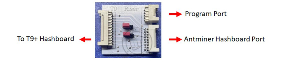 Figure 4: using T9+ Riser to connecting T9+ hashboard to the tester
Whatsminer Hashboard Port: if you want to test a Whatsminer hashboard, connect data cable (PHB2.0 2*7) from that hashboard to this port of the tester. Supported Whatsminer Hashboards are as bellow:
M20, M20s, M21, M21s, M30s, M30s+, M30s++, M31s, M31s+, M32, M32s and any other hashboard with these chips: KF1920, KF1921, KF1922, KF1930, KF1950
Note: if you want to test M3 hashboard, you must use M3 riser. Connect M3 hashboard to the tester according to figure 5.
 Figure 5: using M3 Riser to connecting M3 hashboard to the tester
Innosilicon Hashboard Port: if you want to test a Innosilicon hashboard, connect data cable (PHB2.0 2*7) from that hashboard to this port of the tester. Supported Innosilicon Hashboards are as bellow:
T1, T2, T3, T3+, S3, S3+, T3H, A4, A4+, A6, A6+, T2T, T2T+, T2Ti, T2Ts, T2Tz, T2Tzs, T2Tzu, T2Tza, T2Th, T2Ths, T2Thm, T2Thf, T2Th+, T2Ths+, T2Thm+, T2Thf+, T2Thl+, L1, L2, L2HU, L2HF, L2HL, L2HS, T1H
Cheetah, Aixin Hashboard Port: if you want to test a Cheetah or Aixin hashboard, connect data cable (PHB2.0 2*9) from that hashboard to this port of the tester. Supported Cheetah and Aixin Hashboards are as bellow:
A1, Q3, F1, S5
Innosilicon PSU Port: if you want to test a Innosilicon PSU, connect data cable of the PSU to this port of the tester. Supported Innosilicon PSU are as bellow:
G1138(T2), G1240(T2Tz), G1266(T2Th), G1286(T2Th+), G1306(T3+), QB2412-B(T2Tz), QB2412-C(T2Th)
Antminer PSU Port: if you want to test an Antminer PSU, connect data cable of the PSU to this port of the tester. Supported Antminer PSU are as bellow:
APW8, APW9, APW9+, APW12
Whatsminer PSU Port: if you want to test a Whatsminer PSU, connect data cable of the PSU to this port of the tester. Supported Whatsminer PSU are as bellow:
P20, P21, P21E, P21D, P221C, P222C
Cheetah, Aixin PSU Port: if you want to test a Cheetah or Aixin PSU, connect data cable of the PSU to this port of the tester. Supported Cheetah and Aixin PSU are as bellow:
TT240015P (A1), HQ2500-A02 (Q3)
2. Hashboard Tester
To enter hashboard tester mode, connect input voltage cable to the tester. Then just press On/Off switch. You will see the select hashboard page as bellow:
 Figure 6: select hashboard page
In this figure you can see 3 different categories of hashboards. Antminer, whatsminer and innsosilicon. By pressing green keys, categories can be selected. In each category, different hashboards can be selected by pressing blue keys.
Then, for example we want to select S17. Once you selected S17 option, press the white key to enter in the S17 analyzer page (figure 7).
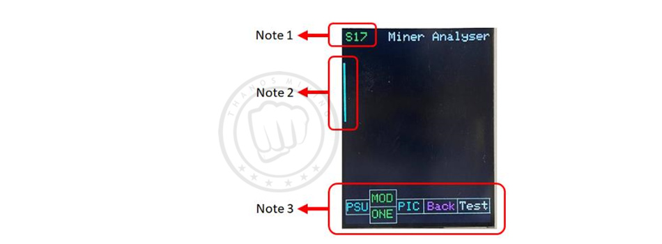 Figure 7: S17 analyzer page
Note 1: in figure 7, the name of the selected hashboard (now is S17) will be displayed here
Note 2: in figure 7, the narrow blue line appeared in the screen, indicates what connector of the tester must be used to connect to the selected hashboard (here is S17).
Note 3: in figure 7, you can see how different keys work.
2.1 Antminer hashboards
in figure 7, you can see how different keys work as bellow: (for example we want to test S17 hashboard)
| PSU |
you can enable the S17 PSU (APW9 with 19v), by pressing PSU buttom. (You must had connected the PSU data cable between the tester and the PSU) |
| MOD |
you can select the mode of testing by pressing MOD buttom. For example, S17 has 2 testing modes: Mode1 and Mode2. (Please refer to figure 11 to know what each mode does for each selected hashboard)
|
| ONE |
if you toggle this buttom, it changes to 999. This means how many times you want to test the hashboard. Once or 999 times repetitively. |
| PIC |
if you toggle this buttom, it changes to PC0 and PC1. If you select PC0, the tester enables PIC microcontroller in the hashboard that consequently the MOSFETs in the hashboard will turn on and then it allows the current to enter in the hashboard. In this situation, RST signal is kept 0v in the hashboard. If you select PC1, PIC microcontroller in the hashboard will be enabaled but RST signal is kept HIGH (1.8v in test points). If you select PIC , it will turn off the MOSFETs in the hashboard.
Note: if you select PC0 or PC1, and then test the hashboard with 999 option, the PIC of the selected hashboard will be turn on as long as you test it. Otherwise, PIC will be turning on and off in each test. |
| Back |
you can go back to select hashboard page, if you press (or hold) Back buttom. |
| TEST |
after you adjust PSU, MOD and ONE options, you can test the hashboard by pressing TEST buttom. |
 Figure 8: an example of toggled keys on the screen of the tester.
After you tested the hashboard, you will see the test result on the screen. (Figure 9)
 Figure 9: the test result of S17 hashboard with condition (Mode1, 1 time test, PSU off)
Note 4: in figure 9, this number indicates how many times the tester, tested this hashboard.
Note 5: in figure 9, This number shows how many chips the selected hashboard should have if it is healthy.
Note 6: in figure 9, This number shows how many healthy chips have been detected by the tester from the first ASIC to the front.
Note 7: in figure 9, This number shows how many healthy chips have been detected by the scope from last ASIC to the test point of revers signal of any chip where you connected the scope probe. (You must connect the + pole of scope probe to the RI/RO (Antminers) or TX (Whatsminers) signal of any chip and connect negative of scope to the negative pole of that chip). You can see 2 examples of the reverse signal test points of Whatsminers and Antminers hashboards in figure 10.
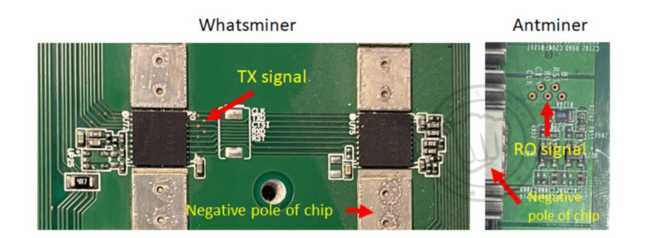 Figure 10: example of the reverse signal test points of Whatsminers and Antminers hashboards
2.1.1 Test modes for Antminer hashboards
PicoBT tester has different test modes for each hashboard. Figure 11, shows these test modes.
 Figure 11, test modes for Antminer hashboards
2.1.2 Test modes for Antminer hashboards
Figure 11, test modes for Antminer hashboards
2.1.2 Test modes for Antminer hashboards
Please note that acceptable input voltages for Antminer hashboards are as figure 12.
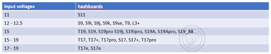 Figure 12, acceptable input voltages for Antminer hashboards
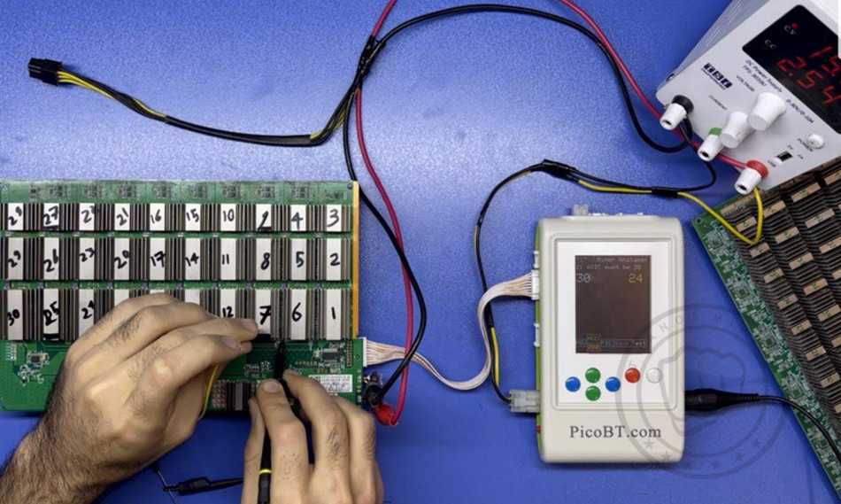
2.1.3 Antminer test example 1
Selected hashboard: T17
Testing mode: Mode1
Test number: 999
30 healthy ASIC detected
24 healthy ASIC detected using scope probe placed in “chip number 12”
Input voltage is 15 volt
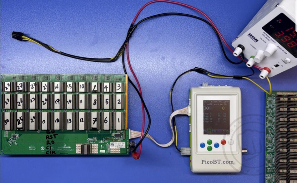
 2.1.4 Antminer test example 2
Selected hashboard: T17
Testing mode: Mode2 (ASIC test, showing temprtures of 4 chips and their coupled external temp. sensor)
Test number: ONE
30 healthy ASIC detected
Input voltage is 15 volt
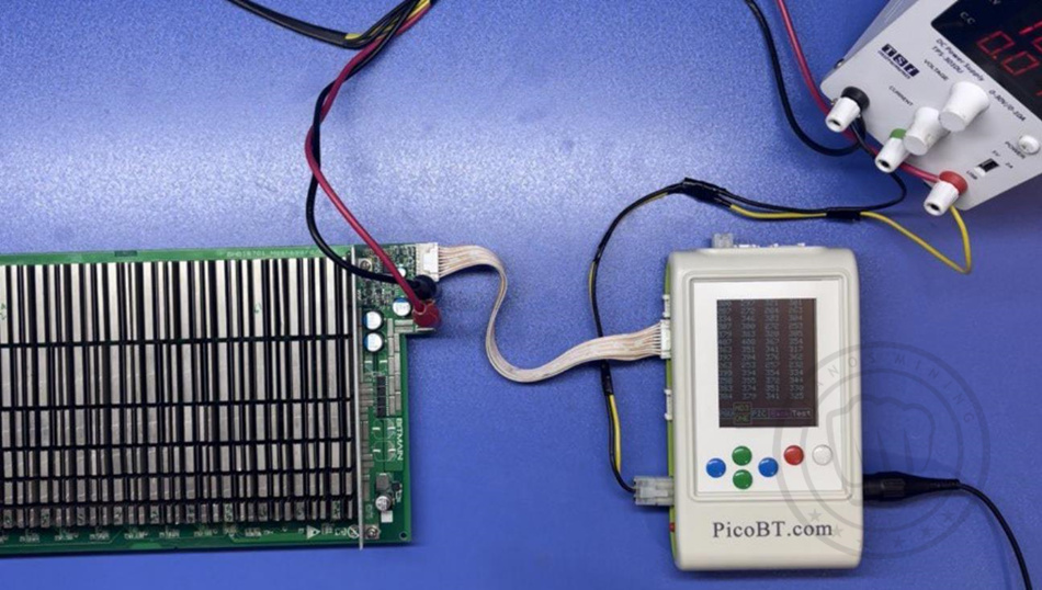
 2.1.5 Antminer test example 3
Selected hashboard: T17e
Testing mode: Mode3 (showing domain voltges)
Test number: ONE
Input voltage is 17 volt
 2.2 Whatsminer hashboards
For example, we want to select M21. Once you selected M21 option from select hashboard page (Figure 6), press the white key to enter in the M21 analyzer page (figure 13).
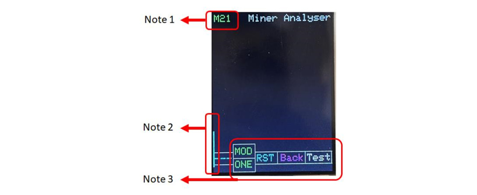 Figure 13: M21 analyzer page
Note 1: in figure 13, the name of the selected hashboard (now is M21) will be displayed here
Note 2: in figure 13, the narrow blue line appeared in the screen, indicates what connector of the tester must be used to connect to the selected hashboard (here is M21).
Note 3: in figure 13, you can see how different keys work.
in figure 13, you can see how different keys work as bellow: (for example we want to test M21 hashboard)
| MOD |
you can select the mode of testing by pressing MOD buttom. For example, M21 has 2 testing modes: Mode1 and Mode2. (Please refer to figure 17 to know what each mode does for each selected hashboard) |
| ONE |
if you toggle this buttom, it changes to 999. This means how many times you want to test the hashboard. Once or 999 times repetitively. |
| RST |
if you toggle this buttom, it changes to RST. This causes the reset signal across the entire hashboard to change from 0 to 1.8 volts. With this option alone, you can test healthiness of the RST signal for all the chips in the hashboard. |
| Back |
you can go back to select hashboard page, if you press (hold) Back buttom. |
| TEST |
after you adjust MOD and ONE options, you can test the hashboard by pressing TEST buttom. |
 Figure 14: an example of toggled keys on the screen of the tester.
After you tested the hashboard, you will see the test result on the screen. (Figure 15)
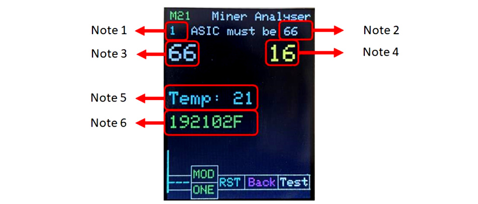 Figure 15: the test result of M21 hashboard with condition (Mode1, 1 time test)
Note 1: in figure 15, this number indicates how many times the tester, tested this hashboard.
Note 2: in figure 15, This number shows how many chips the selected hashboard should have if it is healthy.
Note 3: in figure 15, This number shows how many healthy chips have been detected by the tester from the first ASIC to the front.
Note 4: in figure 15, This number shows how many healthy chips have been detected by the scope from last ASIC to the test point of revers signal of any chip where you connected the scope probe. (You must connect the + pole of scope probe to the RI/RO (Antminers) or TX (Whatsminers) signal of any chip and connect negative of scope to the negative pole of that chip). You can see 2 examples of the reverse signal test points of Whatsminers and Antminers hashboards in figure 16.
Note 5: in figure 15, this number indicates the value of the temperature (centigrade) sensor on the hashboard.
Note 6: in figure 15, this section shows chip model number from EEPROM on the hashboard.
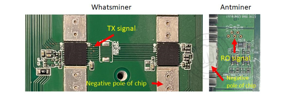 Figure 16: example of the reverse signal test points of Whatsminer and Antminer hashboards
2.2.1 Test modes for whatsminer hashboards
PicoBT tester has different test modes for each whatsminer hashboard. Figure 17, shows these test modes.
Note: hashboards with KF1950 chip, can just be tested with M31 option on the tester.
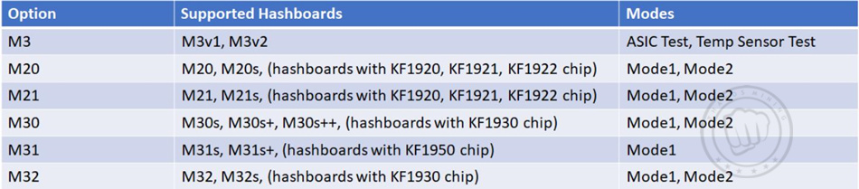 Figure 17, test modes for whatsminer hashboards
Mode1:
Figure 17, test modes for whatsminer hashboards
Mode1:
1) ASIC test (in forward direction)
2) ASIC test (in reverse direction)using scope probe
3)Showing chips model in EEPROM
4) Showing external temp sensor value
Mode2:
1)Testing READ CHIPS MODEL command for chips
(KF1921,KF1921,KF1922,KF1930)
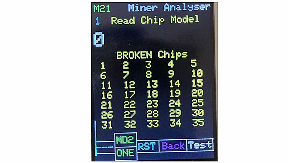 Figure 18, testing READ CHIP MODEL command for whatsminer hashboards (MODE2)
2.2.2 acceptable input voltages
Please note that acceptable input voltages for whatsminer hashboards are as figure 18.
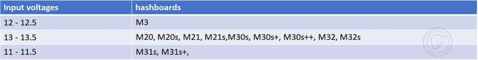 Figure 18, acceptable input voltages for whatsminer hashboards
2.3 Innosilicon hashboards
For example, we want to select T2Tz. Once you selected T2Tz option from select hashboard page (Figure 6), press the white key to enter in the T2Tz analyzer page (figure 19).
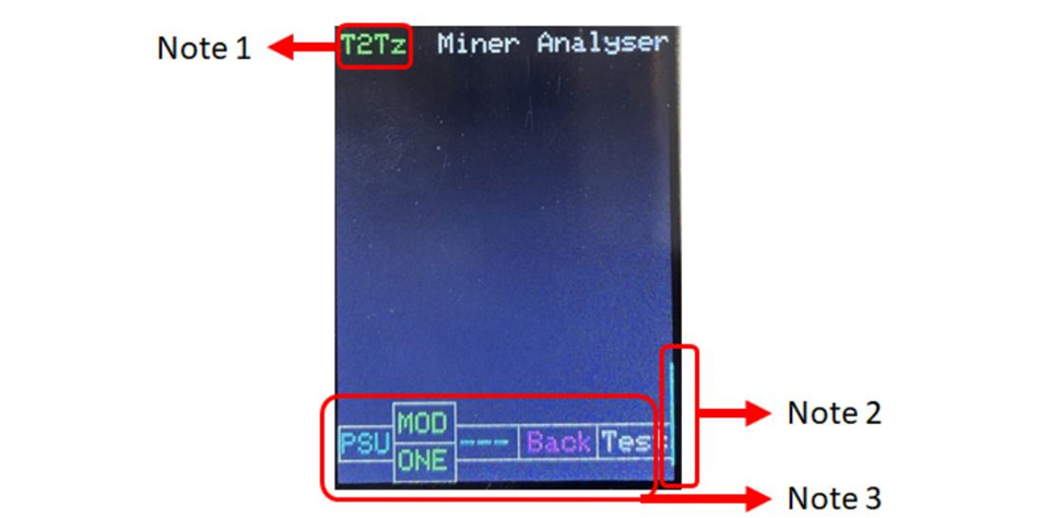 Figure 19: T2Tz analyzer page
Note 1: in figure 19, the name of the selected hashboard (now is T2Tz) will be displayed here
Note 2: in figure 19, the narrow blue line appeared in the screen, indicates what connector of the tester must be used to connect to the selected hashboard (here is T2Tz).
Note 3: in figure 19, you can see how different keys work.
in figure 19, you can see how different keys work as bellow: (for example we want to test T2Tz hashboard)
| MOD |
you can select the mode of testing by pressing MOD buttom. For example, T2Tz has 3 testing modes: Mode1, Mode2 and Mode3. (Please refer to Figure 23 to know what each mode does for each selected hashboard) |
| ONE |
if you toggle this buttom, it changes to 999. This means how many times you want to test the hashboard. Once or 999 times repetitively. |
| PSU |
you can enable the T2Tz PSU (19v), by pressing PSU buttom. (You must had connected the PSU data cable between the tester and the PSU) |
| Back |
you can go back to select hashboard page, if you press (hold) Back buttom. |
| TEST |
after you adjust MOD and ONE options, you can test the hashboard by pressing TEST buttom. |
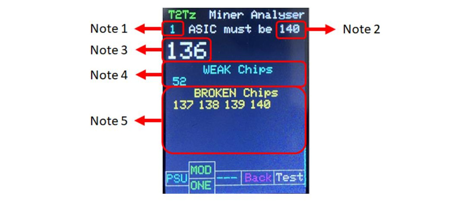 Figure 20: the test result of T2Tz hashboard with condition (Mode1)
Note 1: in figure 20, this number indicates how many times the tester, tested this hashboard.
Note 2: in figure 20, this number shows how many chips the selected hashboard should have if it is healthy.
Note 3: in figure 20, this number shows how many healthy chips have been detected by the tester.
Note 4: in figure 20, this this is number shows the exact number of WEAK chips.
Note 5: in figure 20, this number shows the exact number of BROKEN chips.
If you choose Mode2, after you tested the hashboard, you will see the test result on the screen. (Figure 21)
Note: in Mode2 you can see the temperatures of each chip.
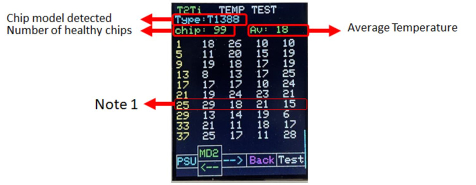 Figure 21: the TEMP test result of T2Tz hashboard with condition (Mode2)
The temperature of all chips for T2Ti hashboard are shown in Figure 21. You can see chip model detected, number of healthy chips, average temperature and also the temperature of each chip in the result.
Note1: in figure 22 you can read the temperature of each chip as bellow:
 Figure 21: how to read the temperature of each chip on the screen (Mode2)
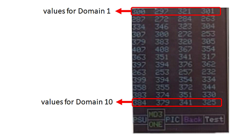
If you choose Mode3, after you tested the hashboard, you will see the test result on the screen. (Figure 22)
note: if you test the hashboard in MODE3, in addition to capability to choose the level of testing accuracy, you will see 4 numbers in the left column of the screen that show you how many chips are determined in these categories (chip models).
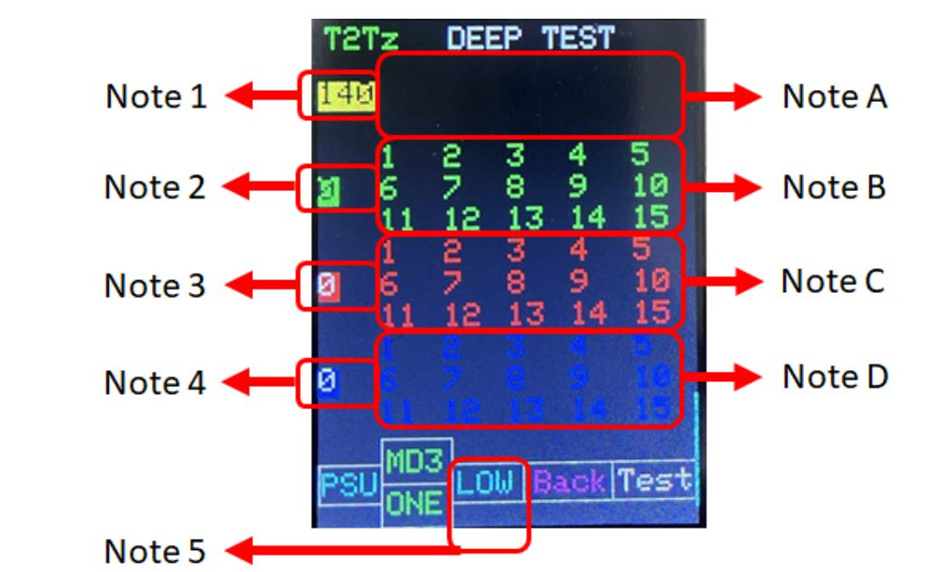 Figure 22: the test result of T2Tz hashboard with condition (Mode3)
Note 1: in figure 22, this number indicates how many are determined in category (chip model 1)
Note 2: in figure 22, this number indicates how many are determined in category (chip model 2)
Note 3: in figure 22, this number indicates how many are determined in category (chip model 3)
Note 4: in figure 22, this number indicates how many are determined in category (chip model 4)
Note 5: in figure 22, by pressing the right blue key, you can select the accuracy level of testing of the hashboard. This 5-level are: LOW, MED, NOR, HIH, FUL
Note A: in figure 22, the numbers in this section are the (first 15 number of) broken chips if chips are determined as chip model 1.
Note B: in figure 22, the numbers in this section are the (first 15 number of) broken chips if chips are determined as chip model 2.
Note C: in figure 22, the numbers in this section are the (first 15 number of) broken chips if chips are determined as chip model 3.
Note D: in figure 22, the numbers in this section are the (first 15 number of) broken chips if chips are determined as chip model 4.
2.2.2 Test modes for Innosilicon hashboards
PicoBT tester has different test modes for each innosilicon hashboard. Figure 23, shows these test modes.
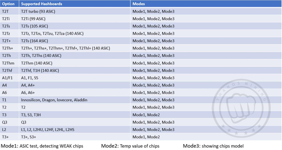 Figure 23: test modes for Innosilicon hashboards
2.3.2 acceptable input voltages
Please note that acceptable input voltages for innosilicon hashboards are as figure 24.
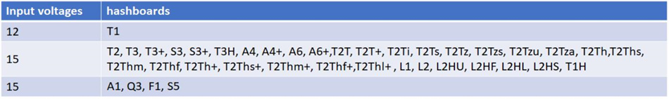 Figure 24: acceptable input voltages for Innosilicon hashboards
3. PSU Tester
To enter the PSU tester mode, First connect input voltage cable to the tester (On/Off switch must be Off). Turn on the switch while you are holding the white key for 2 seconds. You will see a new page on the lcd as bellow (Figure 25)
Figure 24: acceptable input voltages for Innosilicon hashboards
3. PSU Tester
To enter the PSU tester mode, First connect input voltage cable to the tester (On/Off switch must be Off). Turn on the switch while you are holding the white key for 2 seconds. You will see a new page on the lcd as bellow (Figure 25)
 Figure 25: choose PSU tester or EEPROM editor
Now press the red key to enter on PSU Tester. You will see the Power Tester page as bellow (figure 26):
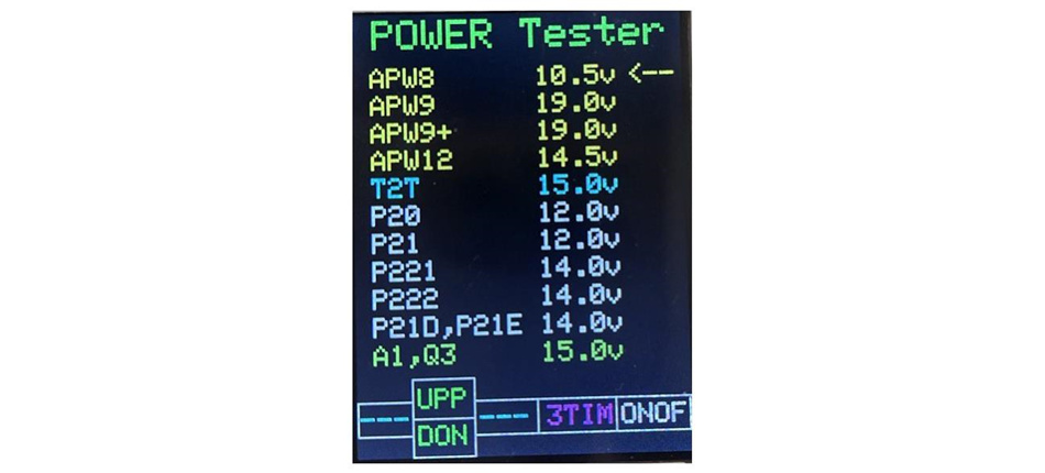 Figure 26: POWER TESTER page
In figure 26 you can select the desired PSU by pressing green keys. After you selected the PSU, you can press the white key to turn on and off the PSU. Also, you can press 3TIM key to turning on and off 3 time repetitively every 2 seconds.
Note: you can enable all innosilicon PSU’s by selecting “T2T 15.0v” option.
4. EEPROM Editor
Copy, flash and save EEPROM contents for Whatsminers and Antminers – you can save 4 EEPROM data in PicoBT tester permanently.
To enter the EEPROM Editor, First connect input voltage cable to the tester (On/Off switch must be Off). Turn on the switch while you are holding the white key for 2 seconds. You will see a new page on the lcd as bellow (Figure 27)
 Figure 27: choose PSU tester or EEPROM editor
Now press the white key to enter on EEPROM Editor. You will see the EEPROM Editor page as bellow (figure 28):
 Figure 28: EEPROM editor page
Note 1: in figure 28, if you select CONNECTED HASHBOARD, you can copy or program (past) data to the hashboard that connected to the tester.
Note 2: in figure 28, any data that you copy from the hashboard or 4 permanent memories on the tester, will be temporary saved on Temporary Memory.
Note 3: in figure 28, there are 4 permanent memories on the tester that you can save 4 EEPROM data in these memories.
Note 4: in figure 28, any data that you copy from any option, will be shown here.
Note 5: in figure 28. you should choose WTS or BIT option by pressing this blue key. If the hashboard is Whatsminer, select WTS, if the hashboard is Antminer select BIT.
You can select the memories by pressing the green keys on the tester.
You can copy the content of any selected memory by pressing the red key on the tester.
You can past the content of any selected memory by pressing the white key on the tester.
Thank you again for choosing ThanosMining products, we will continue to provide you with high-quality products and considerate service.

Previous
AvalonMiner Manual
Read More
Next
Antminer/Whatsminer PSU Wake-up/Startup Tester Manual
Read More


