Avalon Hash Board Repair Manual 82 84 85 Series
By THANOS MINING
May 26th, 2022
 This tutorial applies to Avalon 8 series miners, such as: 821, 841, 851 and other models. Take 821 as an example to explain the precautions and methods of 821 hash board repair.
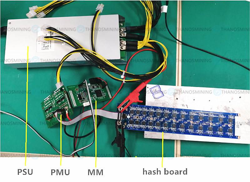
First, we need to understand how to connect the test fixture and hash board. The test fixture consists of 2 parts, namely PMU and MM board (control board)
The connection method is as follows:
————————————————————
PMU connection diagram:
12V power input port: connect to Miner power supply;
VCore and GND: Connect the VCore and GND of the hash board to be tested;
Signal output: connect to the signal port of the hash board to be tested;
Connect with A821MM: Connect A821PMU with A821MM.
 Notice:
1. A821MM is connected to A821PMU. Due to the program setting, the DATA2 interface of A821 is connected to J8 of PMU, and DATA2 pin1 of A821MM corresponds to J8 pin2 of A821PMU;
2. The A821PMU signal and VCore power supply are only output from the J6 connector and the VCore-2 side, so only the J6 side connector and the VCore-2 power output can be connected (as shown in the figure), and it is necessary to pay attention to the interface direction of the A821PMU signal output end, which is the same as the normal plug. The needles are opposite.
Pay attention to the order of 12V power input ports, the top is GND (black), and the bottom is 12V (yellow);
————————————————————
MM board (control board) connection diagram:
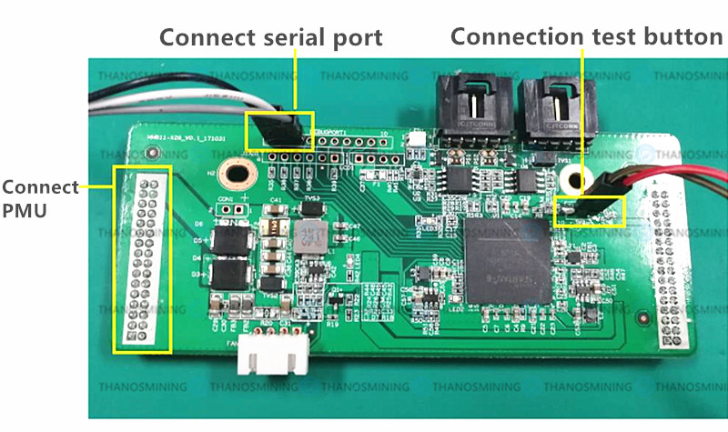 Connect with A821PMU: Connect A821MM with A821PMU;
Serial connection: used to view the Hash board test information on the computer screen, and connected to the computer USB port through the USB to TTL serial port module;
The serial port connection sequence is:
| MM side Pin number |
Serial connection line sequence |
| pin 1 |
GND |
| pin 2 |
TXD |
| pin 3 |
RXD |
————————————————————
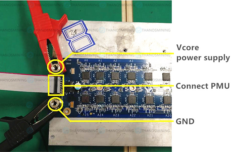
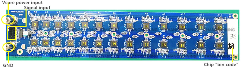
Hash board connection diagram:
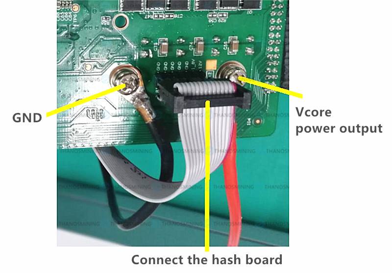
 PMU output connection diagram:
VCore power supply: supply power to the hash board,
GND: Hashboard power GND,
Signal connection between PMU and Hash board: PMU transmits data to Hash board through the connecting line, and then transmits the calculated data back to A821PMU through the data line.
 A821 hash board "pin order":
| pin number |
Signal |
pin number |
Signal |
| pin 1 |
12V |
pin 2 |
1.8V |
| pin 3 |
1.8V |
pin 4 |
RO |
| pin 5 |
GND |
pin 6 |
CO |
| pin 7 |
GND |
pin 8 |
DO |
| pin 9 |
GND |
pin 10 |
DI |
| pin 11 |
GND |
pin 12 |
CI |
| pin 13 |
GND |
pin 14 |
RI |
 Notice:
1. Do not reverse the connection between VCore and GND;
2. The wiring sequence for connecting the PMU and the Hash board; when the signal line is connected, do not insert biased or misplaced, otherwise it will cause damage to the Hash board, MM, and PMU.
3. The red and black power lines and signal lines must be all connected before testing, otherwise the LDO of the hash board will be burned.
4. It is necessary to place a fan to dissipate heat when testing the Hash board;
5. Do not test the hash board for a long time, otherwise the temperature will be too high.
————————————————————
Avalon 821 Hash Board Construction:
When replacing the ASIC chip on the Hash board, it is necessary to replace the chip with the same Bin number according to the chip label of the Hash board.
————————————————————
Hash board test steps:
1. Determine the status of the HASH board
Power on and judge the status of the hash board according to the status of the indicator lights of the MM (control board), and determine whether repair is required:
The status indicator is judged as follows:
Green, the hash board is in normal condition and does not require repair.
Red, the hash board is in an abnormal state and needs to be repaired.
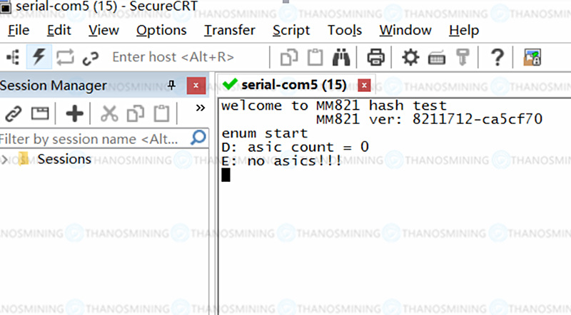
 2. Determine whether there is a problem with the hash board through the serial port
Through the serial port debugging tool, check the LOG information of the hash board running on the computer, as shown in the figure:
The serial port debugging tool setting needs to set the serial port number, and the baud rate is set to 115200, the data bit is 8, and the stop bit is 1.

————————————————————
3. Coretest abnormal phenomenon judgment and repair
If it appears in the LOG information, asic count=26, miner 0 asic 21 pass 0, miner 0 asic 24 pass 0, it means that there is a problem with the A21 and A24 chips corresponding to the A821 computing power board, and the A21 A24-bit chip needs to be replaced.
Note: The BIN number of the chip to be replaced should correspond to the BIN number marked on the back of the hash board.
 4. Loopback abnormal phenomenon and repair
If it appears in the LOG information, asic count=0, it means loopback fail, that is, the link of the hash board is unreachable, it means that there is a problem with the signal transmission of the A821 hash board, and further testing is required.
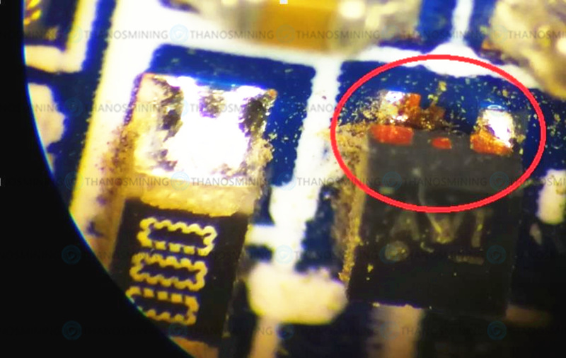
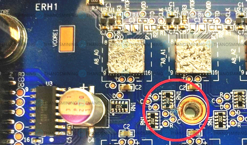
 First of all, we need to visually check whether the appearance of the components is damaged, or the welding is poor,
LDO Soldering Problems:
 Abnormal resistor:
 If it is not visible to the naked eye, an oscilloscope and multimeter are required to quickly locate the hash board problem:
1. You need to use a multimeter to measure the impedance gear. The impedance between the 12V test point and GND. If the impedance is between 0-100Ω, there is a problem with the LDO (U1, U2) of A0-A5.
It is necessary to test the impedance of the A0-A5VTOP test point and the VDD test point to determine whether the impedance is normal. If the impedance does not match, the corresponding LDO (U1, U2) needs to be replaced.
 The resistance values corresponding to U1, U2 and GND are:
| Test point |
Impedance (Ω) |
Corresponding chip |
| VTOP |
>90Ω |
U1 |
| VDD |
>70KΩ |
U2 |
2. Use an oscilloscope to test the Co signal of each group of chips. If there is no waveform, there is a problem with the group of chips. First, you need to use a multimeter to determine whether the output voltage of U1 and U2 meets the impedance value and voltage value. If not, you need to replace the corresponding one. Power chip (U1, U2).
The waveform of Co signal is shown in the figure below:
(The oscilloscope is set to: AC; the amplitude is set to 1.00V/div,The frequency is set to 500ns/div)

————————————————————
A821 hash board parameter reference:
| Signal |
Resistance value (Ω) |
| RO and GND |
365K |
| CO and GND |
365K |
| DO and GND |
365K |
| DI and GND |
234K |
| CI and GND |
234K |
| RI and GND |
234K |
| 12V and GND |
64K |
| 1.8V and GND |
37K |
| RO and CO |
747K |
| CO and DO |
747K |
| DO and DI |
700K |
| DI and CI |
553K |
| CI and RI |
554K |
| C and GND |
1K |
| D and GND |
1K |
| R and GND |
1K |
| Voltage |
Voltage value |
| VDD |
1.8V |
| VTOP |
0.75V |
| Vcore |
0.35V |
1. Since the chip module is in series mode, the signal is transmitted from the 25th chip module to the 0th chip module. It needs to be checked from the 25th chip to the 0th chip. If the previous chip does not work, the subsequent chips will not work. Work;
2. Confirm that the waveforms of the two adjacent signals of each module are not consistent. If they are consistent, you need to confirm the impedance of the adjacent signals to determine whether the pins are short-circuited;
3. The signal voltage of each chip module is 1.8V.

Previous
Avalon 1066pro Test Fixture User Manual
Read More
Next
Antminer/Whatsminer PSU Wake-up/Startup Tester Manual
Read More


 Notice:


